


Other forms of electrical actuators include solenoid, electro-mechanical relay, and contactor, among others. A solenoid can be referred to as a device that converts electrical energy into mechanical energy (motion). It consists of a coil of wire, plunger, and spring. The coil is formed in such a way that the plunger can move in and out of the coil's body. When a current passes through the coil, a magnetic field is created and is used to create a linear or angular motion depending on the type. The spring returns the plunger back to its original position when power is removed. A solenoid is used in an automated system to create motion. An electro-mechanical relay is an electrically operated switch that can open or close a circuit with the physical movement of a contact. It can be referred to as a switch that is operated electrically, unlike the manual or mechanically operated switch. It consists of a coil (electromagnet), a moveable contact, stationary contacts, and a spring. The various types include SPST, SPDT, DPST and DPDT. Relays and contactors have similar basic operations and functions. The main difference is their current handling capacity. Relays can switch smaller current loads of up to about 20 A or more while a contactor can handle larger current loads of up to 12,500 A.
Pneumatic actuators
Pneumatic actuators use pressurized air or gas as an energy or power source to produce rotary or linear motion. They have various industrial applications, which include the regular opening and closing of valves, pick and place handlers, and so on. A pneumatic actuator can also be referred to as a pneumatic cylinder or air cylinder. In a pneumatic actuator, compressed air or pressurized gas enters a chamber, and the gas builds up pressure in contrast to the outside atmospheric pressure, which results in the motion of a device, which could be a piston or gear. The motion created by a pneumatic actuator can be linear or circular. Hence, a pneumatic actuator simply converts the energy in compressed air into a linear or circular motion. Two basic types of pneumatic actuators are pneumatic linear actuator (Single-acting cylinders and Double-acting cylinders) and pneumatic rotary actuator (Scotch yoke, Vane and Rack and pinion).
In a pneumatic linear actuator, compressed air entering a chamber or cylinder builds up pressure and can cause a piston to move forward or backward in a linear motion when the pressure built up in the chamber contrasts with the outside atmospheric pressure. 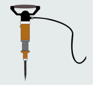
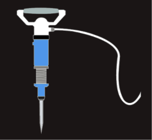 Pneumatic hammer or jack drill is a practical application of a single-acting cylinder of a pneumatic linear actuator type.
A pneumatic rotary actuator rotates rather than moving in a straight line. They can be designed to mount onto a valve that requires the rotation of their stem to open or close the valve remotely or automatically via a control signal.
Hydraulic actuators
Hydraulic actuators use pressurized hydraulic fluid (oil) as an energy source to produce rotary or linear motion for an application consisting of high force and ruggedness. A hydraulic actuator can also be referred to as a hydraulic cylinder. It converts hydraulic energy (that is, the energy of fluid) into motion. It also consists of a cylinder in which a piston connected to a piston rod moves back and forth by pumping hydraulic fluid into a port at one end of the piston or at the other end. Similar to a pneumatic actuator, a hydraulic actuator has two types: Hydraulic linear actuator and Hydraulic rotary actuator. The principle of operation of each type is similar to the pneumatic actuators, only that hydraulic actuators utilize hydraulic fluid (that is, oil) unlike compressed air or gas used in pneumatic systems.
It consists of a cylinder, piston, a piston rod, a spring, and so on. It has only one port for fluid (hydraulic fluid supply) to flow into the cylinder. When the hydraulic fluid enters through this port, the pressure increases and pushes a piston forward for a push type or backward for a pull type. A spring that is positioned in or outside the cylinder returns the piston to its original position to make it ready for another burst of pressure.
So, electric actuators use electricity, pneumatic actuators use compressed air, while hydraulic actuators use pressurized fluid (oil). They all perform actions through motion, which can either be linear or rotational. Some actuators are better suited for a particular application than others. For instance, a hydraulic actuator is useful for tasks requiring high force.
AC and DC Motors
Electric motors are generally used to convert electrical energy into mechanical energy. An electric motor can be referred to as an actuator that converts electricity into motion. Hence, it is an electric actuator. They can be found in our homes in most appliances, such as ceiling fans, standing fans, washing machines, microwaves, electric blenders, electric can openers, toys, and so on. In industry, they are widely used for pumps, blowers, mixers, agitators, conveyors, and so on. The use of electric motors in various equipment and machines in homes and industry has proven them to be among the most important electrical inventions of all time.
An AC motor is a type of electric motor that is powered by alternating current (AC) supplied from a power grid or other AC electricity source.
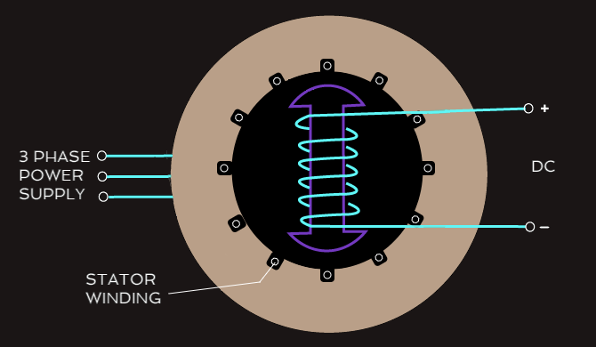
In a synchronous motor, the stator winding is usually connected to a three-phase AC supply. The AC supplied to the stator establishes a rotating magnetic field in the stator and it rotates at synchronous speed. The rotor is supplied with direct current (DC) to make it act as a permanent magnet. Sometimes, the rotor can be made of permanent magnets. Supplying DC to the rotor or making it a permanent magnet makes its magnetic field stationary (that is, the north and south poles are fixed). As the magnetic field of the stator rotates, its poles attract the opposite poles of the rotor and this creates a turning force that causes the rotor to rotate at the same speed as that of the rotating magnetic field (synchronous speed). The term synchronous motor means that the speed of the rotor of the motor is the same as the speed of the rotating magnetic field of the stator. 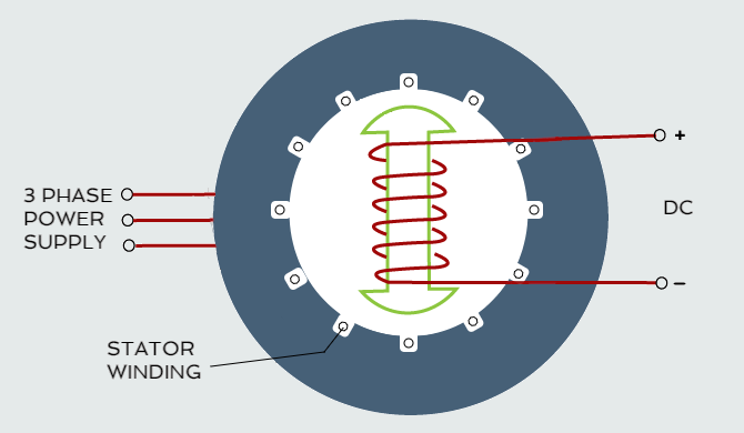
 Synchronous speed = 120f/P
f - frequency [Hz]
P - number of poles
Synchronous motors can be used for applying constant speed from no load to full load. They are good for use in high-precision applications in industry and are also well suited for robotic actuators.
In an asynchronous AC motor (induction motor), the stator winding is usually connected to a three-phase AC supply. The AC supplied to the stator establishes a rotating magnetic field in the stator and it rotates at synchronous speed. The rotor is not directly connected to a supply (that is, there is no electrical connection to the rotor). The rotor current required to produce a turning force is obtained by the electromagnetic induction from the magnetic field of the stator according to Faraday's law of electromagnetic induction, which states that a current will be induced in a conductor placed in a changing magnetic field. The interaction between the rotating magnetic field of the stator and the magnetic field of the rotor creates a turning force that causes the rotor to rotate, but the rotor never runs at the same speed as that of the rotating magnetic field of the stator. An induction motor usually operates more slowly than synchronous speed (the speed of the rotating magnetic field of the stator) since rotation at synchronous speed would result in no induced current in the rotor. 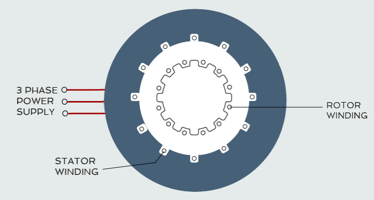
 The difference between the rotor's speed and the speed of the rotating magnetic field of the stator is referred to as slip. One major fact about induction motors is that the rotor current is created by induction instead of being separately excited as in synchronous motors or being self-magnetized using a permanent magnet.
Depending upon the power supply input, there are basically two types of induction motor, which include single-phase and three-phase. Three-phase induction motors are more commonly used in manufacturing and other industries. They have a high starting torque, low costs, low maintenance costs, and are durable. They can be used in conveyors, pumps, blowers, mixers, lifts, crushers, and so on.
A three-phase motor has six terminals (U1 - start1, U2 - end1, V1 - start2, V2 - end2, W1 - start3, W2 - end3) and one earth and can be connected either in star or delta. 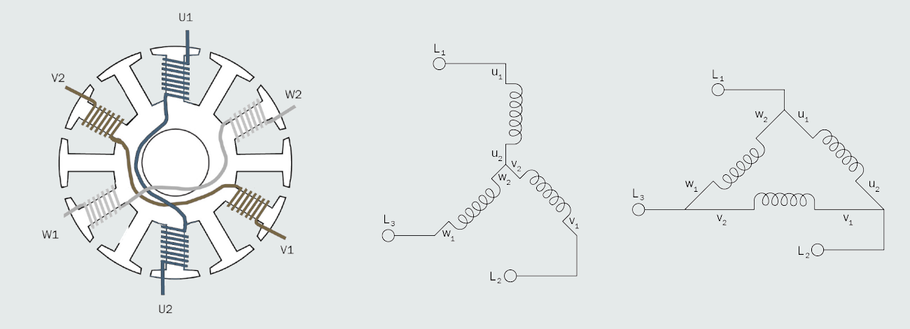
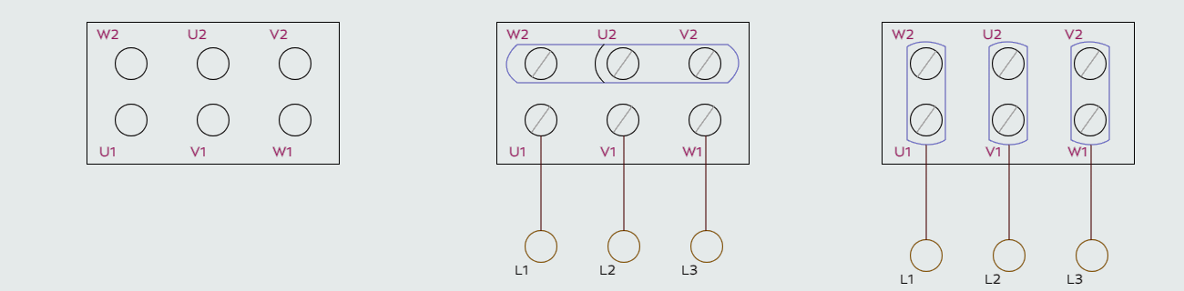
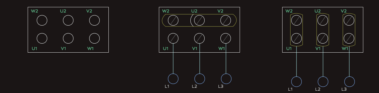 The above diagram shows a three phase motor wiring showing terminal block and jumper bars in star connection (left) and delta connection (right), after the first figure that shows motor terminal block with six terminals. It can be seen that W2, U2, and V2 are connected together via jumper bars and the three phase lines (L1, L2, and L3) are connected to U1, V1, and W1 respectively, making it a star connection. The jumper bars can be rearranged to connect W2 and U1, U2 and V1, and V2 and W1 while still connecting the three phase lines (L1, L2, and L3) to U1, V1, and W1 respectively, making it a delta connection.