


Integrated Circuits (ICs)
An integrated circuit or monolithic integrated circuit (also referred to as an IC, a chip, or a microchip) is a set of electronic circuits on one small flat piece (or “chip”) of semiconductor material, usually silicon. Large numbers of miniaturized transistors and other electronic components are integrated together on the chip. This results in circuits that are orders of magnitude smaller, faster, and less expensive than those constructed of discrete components, allowing a large transistor count. The IC’s mass production capability, reliability, and building-block approach to integrated circuit design have ensured the rapid adoption of standardized ICs in place of designs using discrete transistors. ICs are now used in virtually all electronic equipment and have revolutionized the world of electronics, where each IC is designed for a specific task.
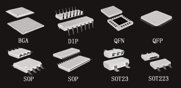
Different ICs have different packages. Some of the most famous packages are dual-in-line package (DIP), surface-mount device (SMD), small-outline IC (SOIC), small-outline package (SOP), quad-flat package (QFP), quad-flat no-leads (QFN), small-outline transistor (SOT), and ball-grid array (BGA). 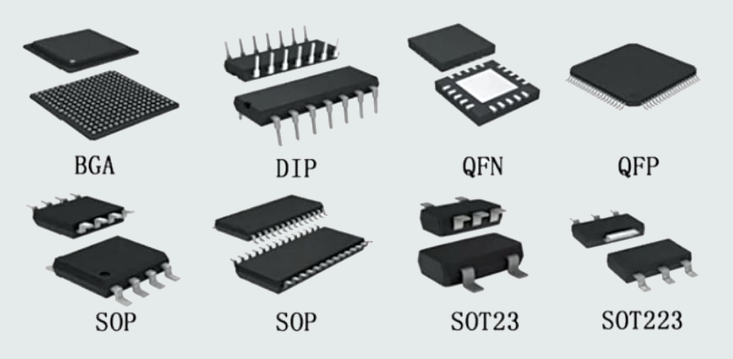
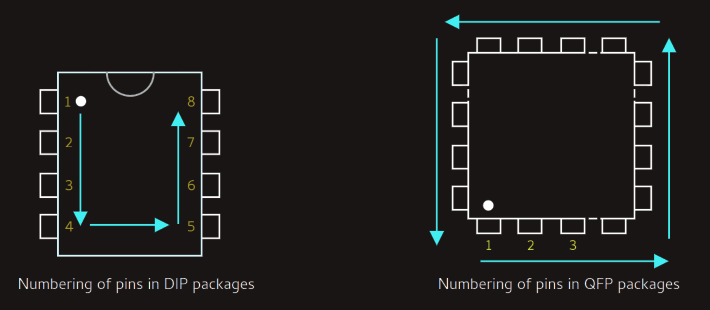
 Most of IC vendors show the first pin of the IC with a small circle.
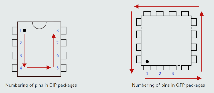
 Each IC has its own datasheet, which contains useful information about that IC. We can use Google to obtain the relevant datasheet.
Capacitors and Inductors
Capacitance is the ability to store energy in the form of an electric field. A capacitor is an electrical component that can store charge. A capacitor exhibits a relatively large amount of capacitance. When a capacitor is first connected to a voltage source, the voltage across the capacitor gradually increases as the current supplied by the source charges the capacitor. During this time, the current in the circuit is gradually decreasing. Eventually, the capacitor will be fully charged, at which point it behaves like an open circuit: no current will flow until something changes and allows the capacitor to discharge.
A capacitor is constructed of two layers, or plates, of conductive material separated by an insulator. When voltage passes through a capacitor, it creates an electric field in the insulating material, called the dielectric, situated between the two layers. The field holds an electric charge in the dielectric.
Capacitors can be dangerous to work with. In some common electronic devices, capacitors hold enough charge to be fatal, and they can hold a charge for quite some time after the device it is connected to no longer works.

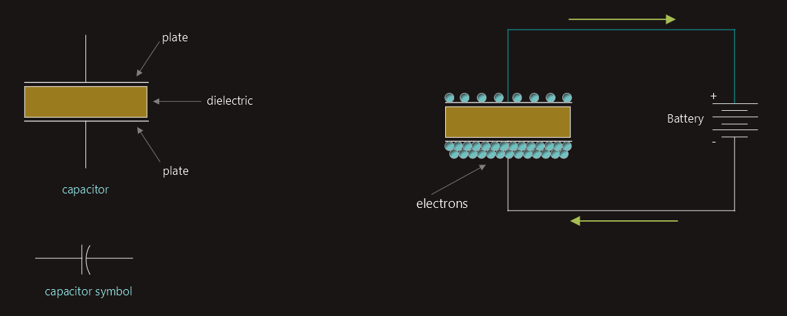
When current flows into a capacitor, the charges get "stuck" on the plates because they can't get past the insulating dielectric. Electrons -- negatively charged particles -- are sucked into one of the plates, and it becomes overall negatively charged. The large mass of negative charges on one plate pushes away like charges on the other plate, making it positively charged. The positive and negative charges on each of these plates attract each other, because that's what opposite charges do. But, with the dielectric sitting between them, as much as they want to come together, the charges will forever be stuck on the plate (until they have somewhere else to go). The stationary charges on these plates create an electric field, which influence electric potential energy and voltage. When charges group together on a capacitor like this, the capacitor is storing electric energy just as a battery might store chemical energy.
When positive and negative charges coalesce on the capacitor plates, the capacitor becomes charged. A capacitor can retain its electric field -- hold its charge -- because the positive and negative charges on each of the plates attract each other but never reach each other. At some point the capacitor plates will be so full of charges that they just can't accept any more. There are enough negative charges on one plate that they can repel any others that try to join. This is where the capacitance [farads] of a capacitor comes into play, which tells us the maximum amount of charge the capacitor can store. If a path in the circuit is created, which allows the charges to find another path to each other, they'll leave the capacitor, and it will discharge.
One of the most common applications of capacitors in large buildings is for power factor correction. When too many inductive loads are placed into a circuit, the current and voltage waveforms will fall out of sync with each other and the current will lag behind the voltage. We then use capacitor banks to counteract this and bring the two back into alignment. Another common application is to smooth out peaks when converting AC to DC. Capacitors are commonly used in power supplies to remove high-voltage surges and to smooth out the voltage after it has been rectified. Capacitors are also used in electric single-phase motors to help them start and develop full torque.
An inductor — also known as choke or coil — is a passive two-terminal electrical component that stores energy in a magnetic field when electric current flows through it. When the current flowing through the coil changes, the time-varying magnetic field induces voltage in the conductor with a polarity which opposes the change in current that created it. As such, inductors oppose any changes in current that pass through them. 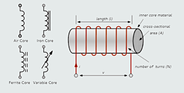
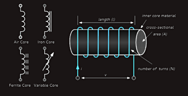 Inductor opposes a change in current. If the current is changing, like in AC, then voltage will be induced across the inductor. As we know already, when an electrical current flows through a wire conductor, a magnetic flux is developed around that conductor. This effect produces a relationship between the direction of the magnetic flux, which is circulating around the conductor, and the direction of the current flowing through the same conductor. But there is also another important property relating to a wound coil that also exists, which is that a secondary voltage is induced into the same coil by the movement of the magnetic flux as it opposes or resists any changes in the electrical current flowing through it. Unlike a capacitor which opposes a change of voltage across its plates, an inductor opposes the rate of change of current flowing through it due to the build up of self-induced energy within its magnetic field.
Capacitor and Inductor differences
One of the main differences between a capacitor and an inductor is that a capacitor opposes a change in voltage while an inductor opposes a change in current. Furthermore, the inductor stores energy in the form of a magnetic field, and the capacitor stores energy in the form of an electric field.
Capacitance is the ability of a device to store electric charge. Inductance is the ability of a device to generate a voltage when the current through it changes. Capacitors and inductors are the main examples of devices that have capacitance and inductance, respectively. Capacitance and inductance are measured in farads (F) and henrys (H), respectively.
Capacitance affects AC and DC circuits in different ways. In a DC circuit, a capacitor acts like an open circuit when it is fully charged or discharged. This means that no current flows through it. In an AC circuit, a capacitor acts like a resistor that depends on the frequency of the AC source. This means that the current through it varies with the frequency. The higher the frequency, the lower the resistance, and vice versa. This is called capacitive reactance.
Inductance also affects AC and DC circuits in different ways. In a DC circuit, an inductor acts like a short circuit when the current is constant. This means that the current flows through it without any voltage drop. In an AC circuit, an inductor acts like a resistor that depends on the frequency of the AC source. This means that the voltage across it varies with the frequency. The higher the frequency, the higher the resistance, and vice versa. This is called inductive reactance.
Capacitor acts as an open circuit to the steady state condition in DC circuits, whereas inductor behaves as a short circuit to the steady state condition in DC; the current is stable and the inductor acts like an ordinary connecting wire.
In a DC circuit when capacitor is added in series with a resistor, the current initially becomes high but later falls to zero. In case of an inductor when it is added in series with a resistor, the value of current is small at the starting but gradually it increases with time.
Capacitors oppose a change in voltage and can block direct current (DC), while allowing alternating current (AC) to pass. This is because the charge stored in the capacitor resists changes in voltage, creating a short-term battery effect. Inductors, however, oppose a change in current. They allow DC to pass easily but resist AC. This is due to the magnetic field created by the current flow, which resists changes in current.
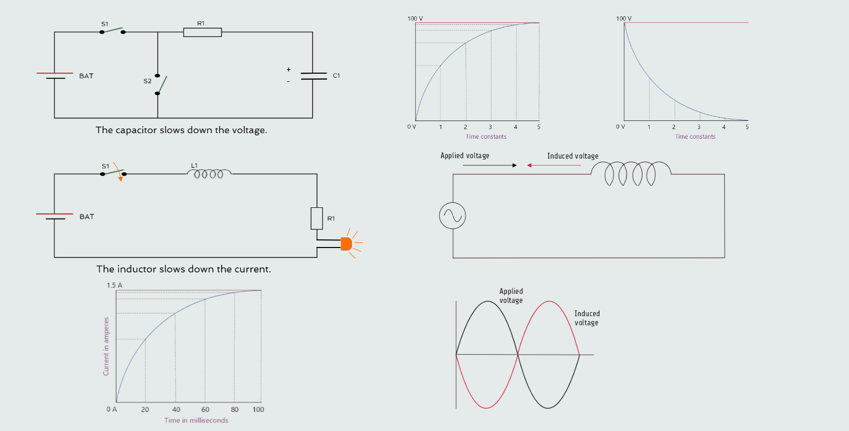
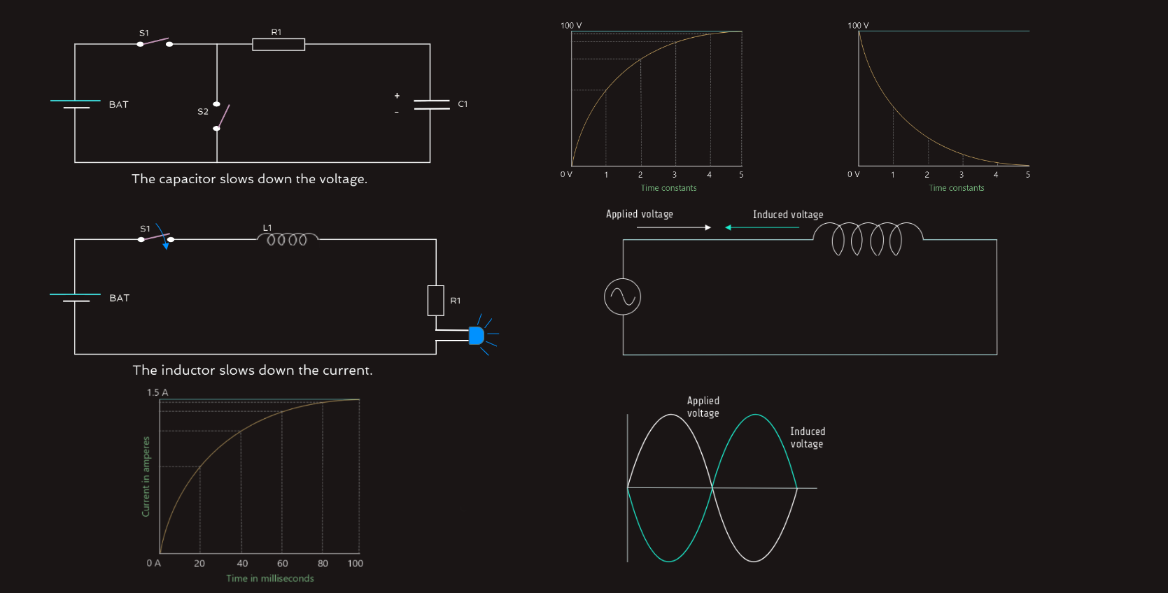
At switching instant, circuit is established and full voltage appears across a circuit. The circuit tries to establish full current as per its parameters immediately on switching. So inductor sees this as a drastic change and tries to oppose it. The nature of inductor reaction demands that it opposes the change with all its capacity, and since there was no current before switching, it tries to maintain that position. This is possible only if it works as open circuit. When the switch is off, there is no current flowing. When we flip the switch on, the battery will try to get current flowing. That means there is a change in current which the inductor will resist. So instead of the current going from zero to maximum right away, it will gradually increase up to its maximum current. Since the current decides the light intensity of the LED in a circuit, the inductor makes the LED fade in instead of turning on instantly. We need a very large inductor to be able to see the LED fade in the circuit above. It’s not something that we’d use an inductor for. But we could use it as a mental image of what the inductor does in a circuit. The inductor also resists the current from switching off instantly. The current won’t just stop flowing in the inductor in an instant. So when we switch off the power, the inductor will try to continue the current flow. It does this by quickly increasing the voltage across its terminals. It actually increases so much that we can get a little spark across the pins of our switch! This spark makes it possible for the current to keep flowing, through the air, for a fraction of a second until the magnetic field around the inductor has broken down. That’s why it’s common to place a diode in reverse across the coil of a relay or a DC motor. This way, the inductor can discharge through the diode instead of creating high voltages and sparks in the circuit.
In steady state DC, there is nothing to oppose, and current is therefore decided by resistance in the circuit. An ideal inductor has zero resistance hence it behaves as short circuit. The inductor activates itself when current changes in the the given circuit; hence when inductor is connected across alternating current then it is always activated. It's one of the main features is that it opposes the change of current in the circuit. So it opposes the alternating current, but when current becomes constant or steady the inductor does not oppose the current since the value of current in circuit this time is constant.
For an inductor connected to an alternating voltage, the magnetic field continually increases, decreases, and reverses polarity. Since the magnetic field continually changes magnitude and direction, a voltage is continually being induced in the coil. This induced voltage is 180° of phase with the applied voltage and is always in opposition to the applied voltage. Since the induced voltage is always in opposition to the applied voltage, the effective applied voltage is reduced by the induced voltage.
While inductors are common in electric circuits, capacitors are more common in electronic circuits.