


Furthermore, let us implement 16x1 Multiplexer using 8x1 Multiplexers and 2x1 Multiplexer. We know that 8x1 Multiplexer has 8 data inputs, 3 selection lines and one output. Whereas, 16x1 Multiplexer has 16 data inputs, 4 selection lines and one output. So, we require two 8x1 Multiplexers in first stage in order to get the 16 data inputs. Since, each 8x1 Multiplexer produces one output, we require a 2x1 Multiplexer in second stage by considering the outputs of first stage as inputs and to produce the final output. 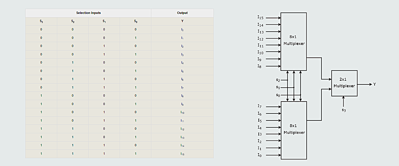
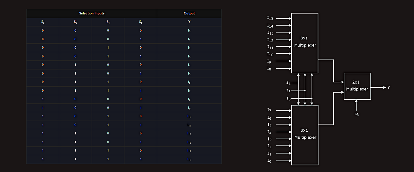 The same selection lines, s2, s1 & s0 are applied to both 8x1 Multiplexers. The data inputs of upper 8x1 Multiplexer are I15 to I8 and the data inputs of lower 8x1 Multiplexer are I7 to I0. Therefore, each 8x1 Multiplexer produces an output based on the values of selection lines, s2, s1 & s0. The outputs of first stage 8x1 Multiplexers are applied as inputs of 2x1 Multiplexer that is present in second stage. The other selection line, s3 is applied to 2x1 Multiplexer:
· If s3 is zero, then the output of 2x1 Multiplexer will be one of the 8 inputs Is7 to I0 based on the values of selection lines s2, s1 & s0.
· If s3 is one, then the output of 2x1 Multiplexer will be one of the 8 inputs I15 to I8 based on the values of selection lines s2, s1 & s0.
Therefore, the overall combination of two 8x1 Multiplexers and one 2x1 Multiplexer performs as one 16x1 Multiplexer.
Port servers
A serial server is a networking device that transfers data between an Ethernet local area network and a computer's or a device's serial port (COM port). The main purpose of a serial server is to allow a serial device such as a printer, scanner or climate control system to be used in a network without relying on the serial port of a computer for connectivity. This allows any serial device to be connected to the network and accessed from anywhere, including from the Internet.
Serial servers are also known as serial port servers or port redirectors.
A serial server is basically a server that transforms any serial device into an Ethernet-capable device that can be used in a network. For example, an old non-network-capable printer that would traditionally only work when attached to a computer's COM port can be transformed into a networked printer and controlled from anywhere by attaching it to a serial server, which, in turn, is connected to the network through Ethernet cables. This is achieved by the serial server through the creation of virtual serial ports (which have actual serial port connector hardware, only the interface is virtual) that mimic the port of the PC, tricking the device into thinking that it is connected to one. The serial server makes the necessary assignment of IP address and TCP ports to the virtual serial port so that devices and users can communicate with the serial device attached to the server, as well as route traffic to the correct serial device.
A serial server can be a very simple device that does not offer any authentication and security, and is there simply to connect the serial device to the network, or it can be a complex device that offers many functionalities similar to that of Ethernet switches and routers.
Depending on the model, a serial server can interface with simple printers, large-format screens, robotic assembly machines, medical equipment, sensors and other industrial equipment that originally could only interface through the serial port.
Registers
Registers are groups of flip-flops that are capable of holding a complete computer word. Data is read from the computer’s data input bus and passed into the register where it is processed and then written to the data output bus. Registers can also be used to shift numbers to the left (doubling) or to the right (halving) for arithmetic purposes. In this mode, they are called shift registers and have special connections within the circuitry to permit this shifting.
Registers are not always connected to a data bus. They are sometimes connected directly to other facilities, such as memory to allow unique addresses for data storage (i.e. direct memory access, or DMA) or to the output for receiving data from it. Some registers may be used in the arithmetic processes and connect directly to adder circuitry, or other specialist circuitry associated with the multiplication or division processes.

Relay Logic Diagrams
Hardwired logic refers to logic control functions that are determined by the way devices are electrically interconnected. Hardwired logic can be implemented using relays and relay ladder schematics. The control scheme is drawn between two vertical supply lines. All the components are placed between these two lines, called rails or legs, connecting the two power lines with what look like rungs of a ladder — thus the name relay ladder schematic.
Hardwired logic is fixed; changeable only by altering the way devices are electrically interconnected.
In contrast, programmable control is based on the basic logic functions, which are programmable and easily changed. These function are used to form instructions that will determine if a device is to be switched on or off. The form in which these instructions are implemented to convey commands to the PLC is called the language.
The most common PLC language is ladder logic, and the program written accordingly is ladder logic program.
The first step in creating a program for a PLC is creating the relay logic diagram. After the relay logic diagram is drawn, it is converted to a PLC ladder logic diagram (LLD), or often called ladder diagram, which is then loaded into the programmable logic controller to define the operations to be performed by the PLC. 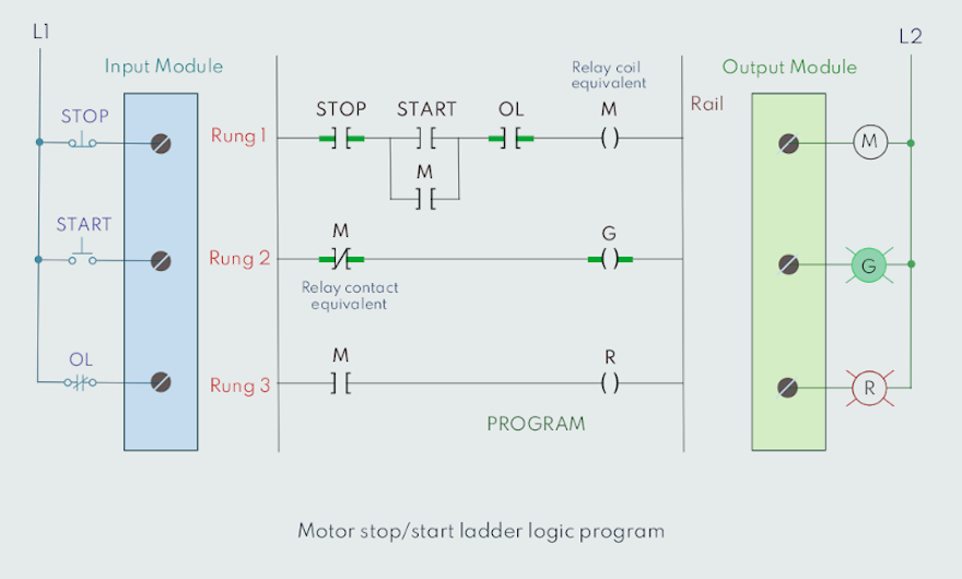
 The instructions used are the relay equivalent of normally open (NO) and normally closed (NC) contacts and coils.
Each rung is a combination of input conditions (symbols) connected from left to right, with the symbol that represents the output at the far right. The symbols that represent the inputs are connected in series, parallel, or some combination of the two to obtain the desired logic.