AC/DC
AC/DC means alternating current and direct current. Before we explain in detail these two terms, let's have a quick look at conventional and electron flow.
We have seen earlier that Benjamin Franklin picked a direction for the flow labeling one side positive and the other negative, before it was known that electrons existed. So current flows from higher potential to a lower potential.
Actually, electrons move in the other direction of what was previously assumed.
By the time all this was figured out, the conventional flow, positive to negative nomenclature, was pretty well established. Since all the basic equations work either way, no one has bothered to change this idea. Instead, another term, electron flow, is used to describe the way electrons actually move in a circuit.
Constant voltage sources - Constant current sources
Devices that cause electrons to move are called sources. The two typical types of sources are voltage and current sources.
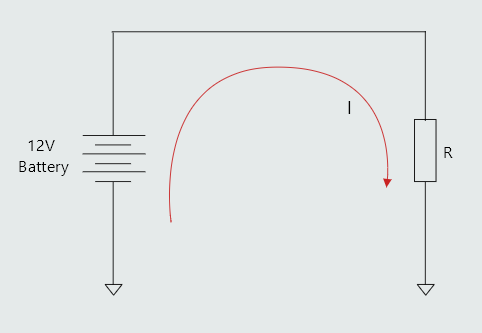
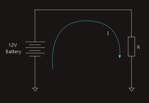
• With a voltage source, the output will try to maintain the voltage across the load. That is, the voltage at the source will be constant. This means in terms of Ohm’s Law that V remains the same at the source. I and R can change, but in the end it must always equal V in terms of Ohm’s Law: V = IR.
• With a current source, the output will try to maintain the current through the load. That is, the current from the source will be constant. Current from the source will remain constant, allowing V to change as R varies, still following Ohm’s Law: I = V/R.
Current sources are less common, but they do exist and can be used in many situations.
Sources can come in two different types: AC or DC.
Direct current
The term direct current is used to describe current that flows in only one direction. Direct current moves only one way, and adopting conventional flow, from positive to negative.
A battery is a common direct-current device.
A DC source will always try to move current in the same direction. One thing to note is that the current coming out of the source always needs to get back to the source somehow. The ground connection on the schematic should be thought of as a label that connects the signal back to the source. If the signal does not get back to the source, then there is no current flow.
Alternating current
Alternating current came about as the interaction of magnets and electricity were discovered. In an AC circuit, the current repetitively changes direction every so often, which means current increases in flow to a peak, then decreases to zero current flow, then increases in flow in the opposite direction to a peak, then back to zero, and the whole process repeats. The current alternates the direction of flow in a sinusoidal fashion.
This type of current most commonly comes from big AC generators. 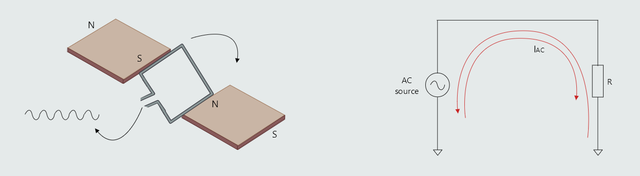
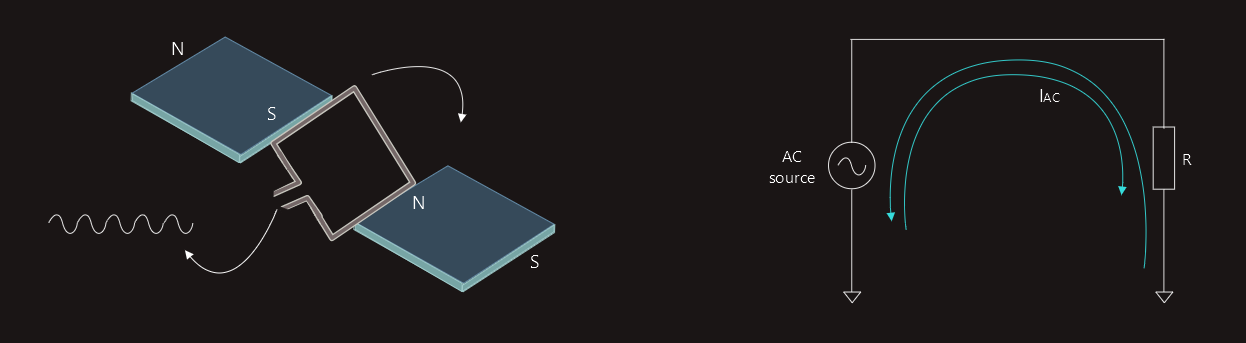 AC power came into being due to this ease of generation. When we move a coil of wire past a magnet, the current first climbs as the strength of the field increases, then as the field decreases and switches polarity, the current also decreases and switches polarity. The voltage and current change in a sinusoidal fashion naturally as the coil passes by the magnets. As long as we keep moving the coil, AC power will continue to be generated.
In AC the voltage could be easily transformed with a transformer which made it possible to level up the voltage so high that the resistance of the distribution wires had little loss over long distances. Although not as famous as Edison, Tesla left a huge legacy in terms of AC power distributions and AC motors.
Capacitors
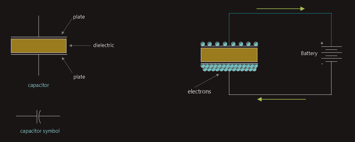
Capacitors are devices that oppose a change of voltage.
The simplest type of capacitor is constructed by separating two metal plates by some type of insulating material called the dielectric. 
 The capacitance of a capacitor is determined by three factors:
1. the surface area of the plates
2. the distance between the plates
3. the type of dielectric used
The greater the surface area of the plates, the more capacitance a capacitor will have.
If a capacitor is charged by connecting it to a DC source shown in figure above, electrons are removed from the plate connected to the positive battery terminal and are deposited on the plate connected to the negative terminal. This flow of current continues until a voltage equal to the battery voltage is established across the plates of the capacitor. When these two voltages become equal, the flow of electrons stops. The capacitor is now charged. If the battery is disconnected from the capacitor, the capacitor will remain charged as long as there is no path by which the electrons can move from one plate to another. So, current can flow only during the period of time that a capacitor is either charging or discharging.
In actual practice, however, capacitor cannot remain in a charged condition forever. No dielectric is a perfect insulator, and electrons eventually move through the dielectric from the negative plate to the positive, causing the capacitor to discharge. This current flow through the dielectric is called leakage current and is proportional to the resistance of the dielectric and the charge across the plates. If the dielectric of a capacitor becomes weak, it will permit an excessive amount of leakage current to flow. A capacitor in this condition is often referred to as a leaky capacitor.
Two other factors that determine capacitance are the type of dielectric used and the distance between the plates.
A capacitor stores energy in an electrostatic field. The electrostatic field is formed when electrons are removed from one plate and deposited on the other.
When a capacitor is not charged, the atoms of the dielectric are uniform, the valence electrons orbit the nucleus in a circular pattern. When the capacitor becomes charged, a potential exists between the plates of the capacitor. The plate with the lack of electrons has a positive charge, and the plate with the excess of electrons has a negative charge. Since electrons are negative particles, they are repelled away from the negative plate and attracted to the positive plate. This attraction causes the electron orbit to become stretched, and this stretching of the atoms of the dielectric is called dielectric stress.
The amount of dielectric stress is proportional to the voltage difference between the plates. The greater the voltage, the greater the dielectric stress. If the voltage becomes too great, the dielectric will break down and permit current to flow between the plates. At this point the capacitor becomes shorted. Capacitors have a voltage rating that should not be exceeded. The voltage rating indicates the maximum amount of voltage the dielectric is intended to withstand without breaking down.
The energy of the capacitor is stored in the dielectric in the form of an electrostatic charge. Capacitors can produce currents of thousands of amperes for short periods of time.
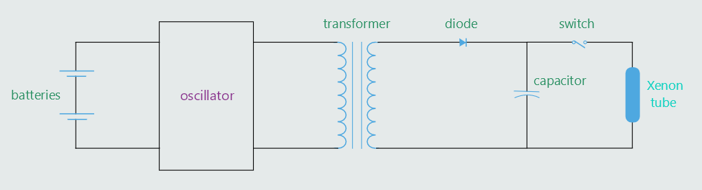
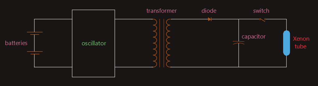
This principle is used to operate the electronic flash of many cameras. Electronic flash attachments contain a small glass tube filled with a gas called xenon. Xenon produces a very bright white light similar to sunlight when the gas is ionized. A large amount of power is required, however, to produce a bright flash. A battery capable of directly ionizing the xenon would be very large and expensive and would have a potential of about 500 volts. The simple circuit shown in figure below can be used to overcome the problem.
In this circuit, two small 1.5 volt batteries are connected to an oscillator. The oscillator changes the DC of the batteries into square wave AC. The AC is then connected to a transformer, and the voltage is increased to about 500 volts peak. A diode changes the AC voltage back into DC and charges a capacitor. The capacitor charges to the peak value of the voltage waveform. When the switch is closed, the capacitor suddenly discharges through the xenon tube and supplies the power needed to ionize the gas. It may take several seconds to store enough energy in the capacitor to ionize the gas in the tube, but the capacitor can release the stored energy in a fraction of a second.