


(5) When taking a reading, the parallax mirror (which runs adjacent to the graduated scale, behind the pointer) should always be used. Its purpose is to ensure that your eye is exactly above the pointer and not to one side or the other. When the eye is exactly above the pointer, the reflection of the pointer is hidden by the pointer.
(6) When the pointer lies between two graduations on the scale, we have to interpolate that reading. By that, we mean that when the pointer is between graduations, we have to estimate whether the pointer is nearer to the lower or the higher graduation, and by how much, in order to place a value on that reading. This requires skill, which comes with practice.
(7) After completing a resistance measurement, a multimeter should never be left on its resistance setting – this is because, should the test-leads become accidentally short circuited, the battery will become de-energized. And, of course: no battery, no ohmmeter!
(8) When transporting an analogue multimeter, if there is no ‘off’ setting, then it should always be set to one of its current ranges – this will allow the instrument to ‘self damp’ through one of its shunt resistances (a lowvalue internal resistor placed in parallel with the meter movement for the purpose of extending its range). Any movement of the coil induces a voltage into the coil, and the direction of the resulting circulating current is such that it always opposes the movement of the coil during transit.
(9) Good quality analogue multimeters are far more rugged than they may appear, but they should always be treated carefully when they are transported in order to avoid damaging their movement. One of the biggest problems occurs when the meter movement is displaced from its bearings.
Following the above steps and being able to interpolate between graduations on an analogue scale are essential skills we all need to acquire when using analogue instruments.
Digital measuring instruments
Digital multimeters have now largely replaced analogue multimeters. In fact, with very few exceptions, analogue instruments are no longer being manufactured. The term ‘digital’ applies not only to an instrument’s liquid-crystal readout, but also to the technology it employs internally.
Analogue instruments have long-reached the limits of their development – the accuracy of their movements and their ease of reading have become about as good as they can possibly get. Digital instruments have now overtaken analogue instruments in terms of their robustness, potential accuracy and the elimination of reading errors. Some digital multimeters can also measure additional quantities, such as frequency, capacitance, etc.
Let’s briefly compare digital multimeters with analogue multimeters:
Analogue multimeters have several scales for measuring current, voltage and resistance and, often, separate scales for measuring a.c. and d.c. They are, therefore, relatively difficult to read, require practice and, consequently, are prone to mistakes by the user - such as reading from the wrong scale or wrongly interpolating a particular reading.
Digital multimeters, on the other hand, have a single, simple, digital readout (often with automatic range adjustment), which is very easy to read, removing the need to interpolate and virtually eliminating the chance of making a reading error.
Analogue multimeters movements are relatively delicate and must be treated with care to prevent them from becoming miscalibrated or their movement damaged.
Digital multimeters, however, are tough and robust, and are far less likely to become damaged. Even relatively severe external physical damage is unlikely to affect their accuracy.
Analogue multimeters require a careful set-up routine prior to taking a measurement, as explained in the previous section.
Digital multimeters must be set to the appropriate function setting (current, voltage or resistance), but many types will then automatically select the most appropriate range within that function, will compensate for an aging battery and all will automatically self-zero when set to measure resistance.
Analogue multimeters require a battery only to measure resistance, and will read current and voltage without a battery.
Digital multimeters, though, require a battery for all their functions, and will not operate at all once the battery is exhausted.
All analogue instruments are, essentially, ammeters which can be adapted to measure voltage and resistance.
Digital multimeters on the other hand are, essentially, voltmeters which can be adapted to measure current and resistance.
So, for digital instruments to measure current, they measure the voltage drop across a very accurate internal resistance; since current is directly proportional to voltage, the readout is calibrated in amperes. To measure resistance, they pass a constant current through the unknown resistance and measure the resulting voltage drop, which is directly proportional to the resistance, and the readout is calibrated in ohms. The operating principle of an actual digital multimeter is significantly more complicated than this explanation – as it must be capable of measuring a.c. as well as d.c. voltages and currents over a wide range of values, as well as measuring resistance and, in some cases, other quantities too.
There is an enormous range of digital multimeters available from a great many manufacturers: from inexpensive consumer-level models to very expensive professional models. They all measure d.c. and a.c. voltages and currents, as well as resistance, but many will also have additional features, enabling them to measure frequency, capacitance, inductance, etc., and to test electronic components such as diodes and transistors.
Digital instruments, in conclusion, are far easier to use, and less error-prone, than their analogue equivalent.
The Oscilloscope
In many cases, it is necessary to know not only the amount of voltage present at a particular point but also the length or duration of the pulse and its frequency. Some pulses may be less than one volt and last for only a millisecond. Therefore we use an oscilloscope to learn what is actually happening in the circuit. The oscilloscope is actually a voltmeter. It does not measure current, resistance, or watts. The oscilloscope measures an amount of voltage during a period of time and produces a two-dimensional image.
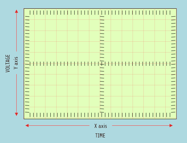
Oscilloscopes can be divided into two main types: analog and digital. They can display both positive and negative voltages, and, also, many oscilloscopes have the ability to display more than one voltage at a time. Each voltage is generally referred to as a trace or channel. Many digital-type oscilloscopes have the ability to display a different color for each trace. Since the oscilloscope has the ability to display the voltage with respect to time, it is possible to compute the frequency of the waveform and display the value, accordingly. The frequency (f) of an AC waveform can be found by dividing 1 by the time (t) it takes to complete one cycle (f = 1/t). Most oscilloscopes use a probe that acts as an attenuator. An attenuator is a device that divides or makes smaller the input signal. An attenuated probe is used to permit higher voltage readings than are normally possible. For example, most attenuated probes are 10 to 1. This means that if the voltage range switch is set for 4 volts per division, the display would actually indicate 40 volts per division. If the voltage range switch is set for 2 volts per division, each division on the display actually has a value of 20 volts per division.
Small sources of electricity
ELectric current is not electrons moving only through the wire because many processes depend on electric current flowing through a gas or liquid. Batteries, for example, would not work if conduction could not take place through a liquid, and fluorescent lighting operates on the principle of conduction through a gas. Conduction through a gas or liquid does not depend on the flow of individual electrons, as it is the case with metallic conductors. Conduction in gases and liquids depends on the movement of ions.
An ion is a charged atom; when atom has deficiency of electron, it is positive ion - in the contrary, when it has gained extra electron, it is negative ion.
A good example of ionization process is the one that happens when combining two atoms: magnesium and chlorine. The result is metallic salt, called magnesium chloride, which is similar to table salt (sodium chloride). If either of these salts is mixed with non-conducting liquid, such as distilled water, it will become a conductor. There are, also, other types of ions, that are formed from groups of atoms and they are useful to the electric industry...
Electroplating is the process of depositing atoms of one type of metal on another. One of the most common uses for electroplating is the production of pure metals.
The term electrolysis refers to the process of separating elements electrically. Elements are often chemically combined with other elements and must be separated. For example, extracting aluminum from compound aluminum oxide, i.e. separating the aluminum and oxygen atoms electrically. In this process, electrons are removed from oxygen ions and returned to aluminum ions. The aluminum ions then become aluminum atoms.
At atmospheric pressure, air is an excellent insulator. If we connect two electrodes, that are separated by an air gap, to a variable voltage power supply and assuming that the output voltage of the power supply is zero when the switch is turned on - as the output voltage is increased, the ammeter will remain at zero until the voltage reaches a certain potential. Once this potential has been reached, an arc will be established across the electrodes and current will begin to flow.
Conduction in a gas is different from conduction in a liquid or metal. The most important factor in the ionization of a gas is electron impact. Electron impact frees other electrons from gas molecules. Under high pressure, electron can travel only a short distance between impacts with gas molecules, whilst under low pressure, electron can travel a greater distance before striking a gas atom. Often, when an electron strikes a gas molecule that does not have enough energy to release other electrons, the molecule will emit light to rid itself of the excess energy. The color of the light is characteristic of the type of gas. Another usage of ionization in a gas are X-rays. Device that operates on the principle of conduction in a gas was invented in 1895 by Wilhelm Roentgen. Also, there is cathode ray tube, operating on the principle of conduction in a gas.
One of the most familiar phenomena in nature caused by ionization of gas is the aurora borealis, or northern lights.
Cells and batteries
After electromagnetism, electrochemical action provides us with our second most important source of electrical energy. Thanks to electrochemical cells, we can use many of our electrical tools, small appliances, multimedia equipment and other gadgets without having to keep them permanently plugged into our wall sockets! Although, of course, we will still require the wall socket to regularly re-energize those cells. As well as powering our mobile phones and other electrical gadgets, cells and batteries are used to start our cars, propel submarines, provide emergency lighting, and many other applications...
An electrochemical cell uses a chemical reaction to release the energy necessary to separate charges, thus creating a potential difference across its terminals. This potential difference is then responsible for causing a drift of electric charges (free electrons) around the external circuit. These charges, of course, already exist in the conductors of the external circuit, and are not ‘injected into it’ by the cell! So what an electrochemical cell does not do, is to ‘store electric charges’ which it then ‘pumps around’ its external circuit. It is, therefore, techically incorrect to say that a cell ‘stores charge’, or that a cell ‘discharges’, or that a secondary cell can be ‘recharged’. We will be using more appropriate terms – e.g. we will say that a cell ‘stores energy’, that a cell ‘de-energizes’, that a secondary cell can be ‘re-energized’ and so on.
Three components that must be present in all types of chemical cell are two dissimilar electrodes and an electrolyte (a dilute acid or alkaline).


Electrochemical cells are either ‘galvanic’ or ‘electrolytic’.
A ‘galvanic cell’ creates a potential difference across its terminals, through the process of charge separation by the release of energy due to the chemical reaction between its electrodes and the electrolyte.
An ‘electrolytic cell’, on the other hand, uses electricity to decompose its electrolyte, a process called ‘electrolysis’, usually for the purpose of electroplating – such as silver or chromium plating.
So, a ‘galvanic cell’ produces electrical energy, whereas an ‘electrolytic cell’ uses or absorbs electrical energy.