


Series circuits
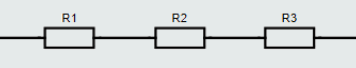
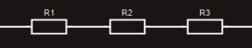
If a number of different circuit components are connected ‘end-to-end’ (or ‘daisy-chained’), so that there is only one continuous path for the current to flow along, then these components are said to be connected in series. The disadvantage with a series circuit is that if there is a break anywhere in the circuit, then no current can flow.
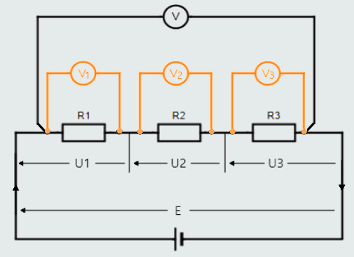
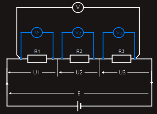
Any number of components can be connected in series, but for convenience here we will consider a circuit with three components (resistances) R1, R2 and R3.
Current in a series circuit
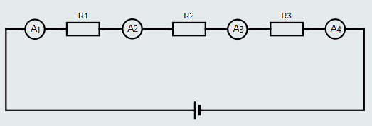
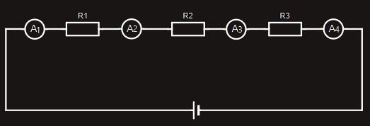
In a series circuit, because there is only one path for the current to flow along, the same current must flow through each component. We say that ‘the same current is common to each component’. Wherever we place an ammeter (a current-measuring instrument) in the circuit, it will give exactly the same reading because it’s measuring exactly the same current – each of the ammeters in the series circuit shown in figure below will register exactly the same value.
Voltage drops in a series circuit
If we placed four voltmeters (instruments for measuring voltage) across each resistance we would find that the sum of the voltage readings across each resistance would equal the supply voltage. The amount of voltage necessary to push the current through each resistor is indicated by the meter, and the supply voltage is the potential difference across the circuit.
These individual voltage readings are termed voltage drops, and are the product of the current through the individual resistance and that resistance (U = IR).
This relationship is credited to Kirchhoff, who realized that the sum of the voltage drops around any closed path is equal to the supply voltage, that may be expressed as follows: E = U1+U2+U3.
From Ohm’s Law we know that E or U = IR, so for our example we have:
IRT = IR1+IR2+IR3
Since the current is common to each resistance, we can divide throughout by I as following: (IRT)/I = (IR1+IR2+IR3)/I.
So, we get RT = R1+R2+R3
RT - total resistance of the circuit
The total resistance for a series circuit is simply the sum of the individual resistances: RT = R1+R2+R3 + etc.
If there is a gap in a series circuit (e.g. when a lamp is removed), the voltage across that gap will be equal to the circuit’s supply voltage! At mains level (i.e. 230 V) or higher supply voltages, an open circuit occurring in a series circuit, could result in a potentially hazardous situation. As no current flows, no voltage drops (i.e. the product of current and resistance) can occur across the healthy resistors – leaving the full circuit voltage to appear across the break in the circuit!
Let's take a look at the circuit above, and let's assume that R3 fails and creates an open circuit. Since no current can now flow, then: U1=0 and U2=0.
Because E = U1+U2+U3, we can express U3 as: U3 = E-U1-U2, U3 = E-0-0, so finally U3 = E.
Potential hazard when working with series circuits! In the event of an open circuit in a series circuit, the full supply voltage will appear across the break in the circuit – creating a potentially hazardous situation.
Series circuits in practice
A very useful application for a series circuit is as a ‘voltage divider’.
Voltage dividers are widely-used in electronics’ circuits, where a single d.c. voltage source is often required to provide lower voltages to various load circuits fed from the same supply. In an a.c. circuit, this would be easily achieved by using a transformer, which are alternating-current machines and they do not work with direct current.
A simple voltage divider consists of the load circuit, which it supplies, connected in series with a ‘dropping resistor’, connected across a d.c. voltage source. A voltage divider works on the principle that sum of the voltage drops across a series circuit must equal the applied voltage. Voltage dividers are used to provide different voltages between certain points in circuit, and they can be constructed to produce any desired voltage.
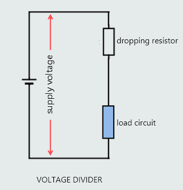
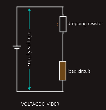
In the figure we have represented the load circuit as a simple resistance but, it could be anything – including, for example, a lamp, a transistor circuit, or some other electronic device or circuit. But, whatever it is, we shall assume that this load circuit is drawing a load current from the supply.
Example:
Suppose we have a particular load circuit that requires a constant operating voltage of 15 V at which it will normally draw a continuous load current of, say, 20 mA. Assuming that the supply voltage is 25 V, what value of dropping resistor will be required to achieve the necessary voltage reduction across the load circuit?
Solution:
Rload = Uload/Iload
Rload = 15[v]/(20x10-3)[A]
Rload = 750[Ω]
In order to drop the supply voltage of 25 V down to 15 V across the load circuit, the amount of voltage we must ‘lose’ across the dropping resistor is:
Udropping resistor = E-Uload
Udropping resistor = 25[V]-15[V] = 10[V]
So, now we can determine the necessary resistance of the dropping resistor:
Rdropping resistor = Udropping resistor/Iload
Rdropping resistor = 10[V]/(20x10-3)[A]
Rdropping resistor = 500[Ω]
So, by placing a 500 Ω resistor in series with our load circuit, we have achieved our aim to provide a voltage of 15 V across that load circuit. This ‘voltage divider’ method of supplying a lower voltage to a load circuit is simple, effective, and widely-used in electronic circuits — providing the load current is constant, and not variable!
But, if the load current does change (due, for example, to a change in the resistance of the load circuit), then the voltage drop across the dropping resistor will also change – resulting in a change in the voltage being applied to the load circuit.
Let’s look at what will happen if the load current, described in the above example, should change from 20 mA to, say, 10 mA.
Udropping resistor = Rdropping resistor x Iload
Udropping resistor = 500[Ω] x (10 x 10-3)[A]
Udropping resistor = 5[V]
which, in turn, will cause the voltage across the load circuit to rise to:
Uload = Esupply-Udropping resistor
Uload = 25[V]-5[V] = 20[V].
And this increase in load voltage is too high, then it could cause the load circuit (which was designed to operate at 15 V) to fail! The worse-case scenario would be for the load current to fall to zero, in which case no voltage drop will appear across the dropping resistor and the full 25 V supply voltage will be applied to the load circuit, almost inevitably causing to it to break down.
This can be prevented from happening by connecting what is termed a ‘bleed resistor’ in parallel with the load.
The resistance-value of the bleed resistor is chosen to draw a continuous current of between 10 – 25% of the total current drawn from the supply. This will guarantee a continous current through the dropping resistor in the event of the load current drawn by the load circuit falling to zero, thus guaranteeing a voltage drop across the dropping resistor, and preventing the load voltage from rising to that of the supply voltage level.
Parallel circuits
When individual components are connected in a way where there is more than one path for current flow, then the components are said to be connected in parallel. Each of these individual paths is termed a branch. One advantage of a parallel circuit is that, should a break occur in one branch, it will not affect the operation of the components in the other branches, as they are still connected to the supply voltage.
Any number of components can be connected in parallel, but we will consider a parallel circuit with just three components each having resistances labelled R1, R2 and R3.
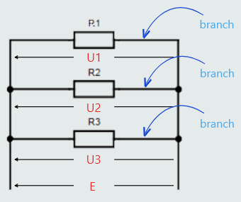
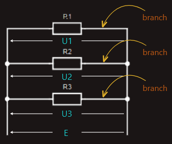
The supply voltage (E) applied across a parallel circuit is common to each branch – regardless of the number of branches.
E = U1 = U2 = U3 = etc.
This complies with Kirchhoff’s Voltage Law, where each branch represents an individual closed loop, so the voltage drop across a component in an individual branch will equal the supply voltage.
This is the second major advantage of a parallel circuit, and is the reason why most everyday circuits are connected in parallel – it ensures that the same voltage is applied across every component.
For example, every circuit in a house is connected in parallel, ensuring that 230 V (or 120 V in North America) will appear across every component (individual lamps, socket outlets, etc.).