

RLC parallel circuit
When an AC circuit contains elements of resistance, inductance, and capacitance connected in parallel, the voltage dropped across each element is the same. The currents flowing through each branch will be out of phase with each other. 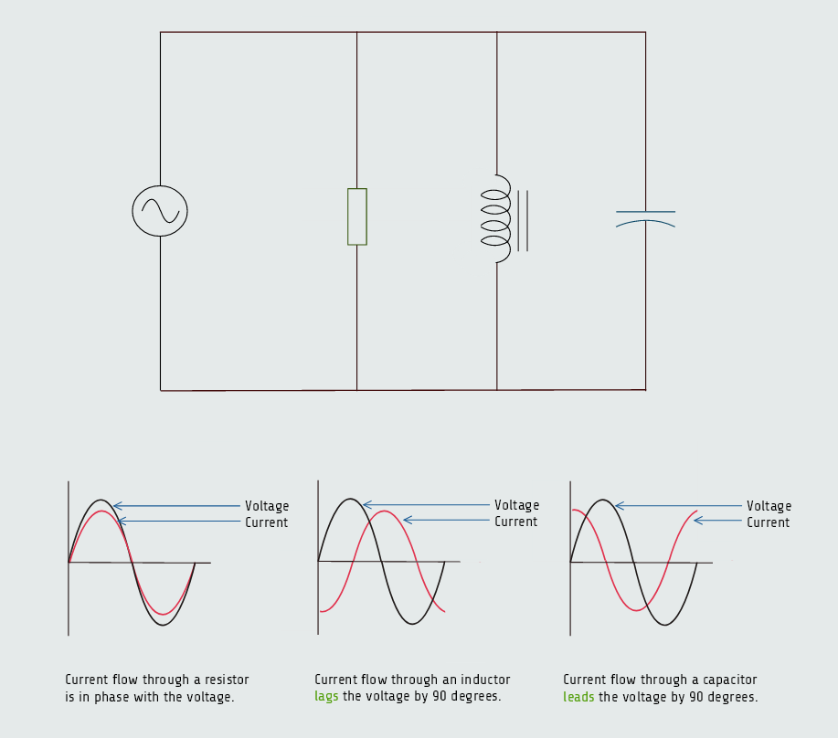
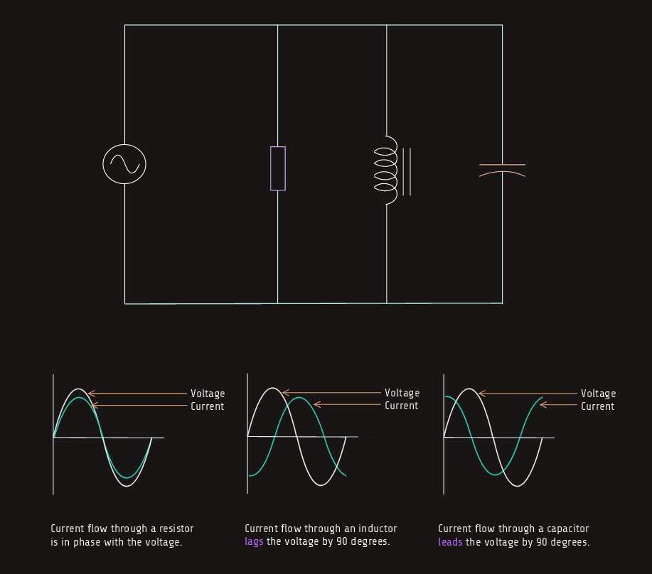 The current flowing through a pure resistive element will be in phase with the applied voltage. The current flowing through a pure inductive element lags the applied voltage by 90 electrical degrees, and the current flowing through a pure capacitive element will lead the voltage by 90 electrical degrees. The phase angle difference between the applied voltage and the total current is determined by the ratio of resistance, inductance, and capacitance connected in parallel. As with an RLC series circuit, if the inductive VARs is greater than the capacitive VARs, the current will lag the voltage and the power factor will be lagging. If the capacitive VARs is greater, the current will lead the voltage and the power factor will be leading.
Impedance
The impedance of the circuit is the reciprocal of the sum of the reciprocals of the legs. Since these values are out of phase with each other, vector addition must be used and we have:
Z = 1/√((1/R)2 + ((1/XL)-(1/XC))2)
The amount of total current flow in the circuit can be computed by vector addition of the current flowing through each leg of the circuit. The inductive current is 180° out of phase with the capacitive current. These two currents tend to cancel each other, resulting in the elimination of the smaller and reduction of the larger. The total circuit current is the hypotenuse of the resulting right triangle. 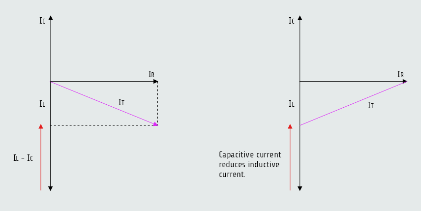
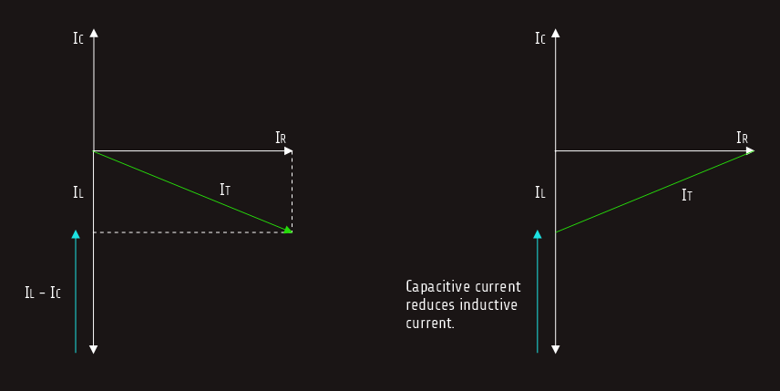 IT = √(IR2 + (IL-IC)2)
IT = E/Z
The apparent power or VAs, can be found using the formula:
VA = E x IT
VA = √(P2 + (VARsL-VARsC)2)
The power factor is PF = W/VA x 100 [%] and for angle θ we know that cos ∠θ = PF.
When values of inductive reactance and capacitive reactance become equal, they are said to be resonant. In a parallel circuit, inductive current and capacitive current cancel each other because they are 180° out of phase with each other. This produces minimum line current at the point of resonance. An LC parallel circuit is often referred to as tank circuit.
Computing the values for a parallel resonant circuit is a bit more involved than computing the values for a series resonant circuit. In theory, when a parallel circuit reaches resonance, the total circuit current should reach zero and total circuit impedance should become infinite because the capacitive current and inductive currents cancel each other. In practice, the quality (Q) of the circuit components determines total circuit current and, therefore, total circuit impedance, Q = ITANK/ILINE .
The amount of current circulating inside the tank is equal to the product of the line current and the Q of the circuit.
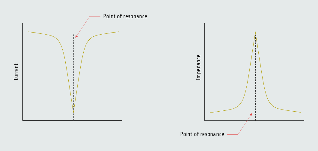
Unlike series resonant circuits which minimize impedance and maximize current at resonance, a parallel resonant circuit achieves maximum impedance and minimum total line current at its resonant frequency. Resonance in a parallel network occurs when the reactive effects of the inductor and capacitor cancel each other out.
* In a series RLC circuit, everything shares the same current. The total impedance is the sum of the individual resistances and reactances: Z = R + j(XL - XC). At resonance: XL = XC, so the reactive part becomes zero: (XL - XC) = 0.
The reactances completely vanish, leaving only R. Since R is the smallest possible resistance in that circuit path, the total impedance drops to its absolute minimum (Z = R). Low impedance means maximum current flows.
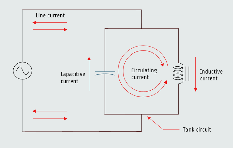
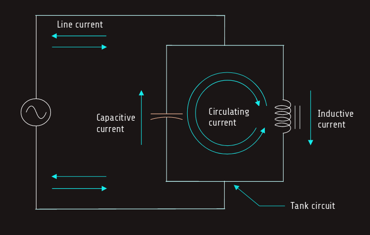
* In a parallel RLC circuit, everything shares the same voltage, but the currents split into different branches. The source has to supply the total current, which is the sum of the branch currents: Itotal = IR + IL + IC. At resonance the inductive branch current (IL) and the capacitive branch current (IC) are equal in magnitude, but they are 180 degrees out of phase (one leads, one lags). Because they are 180 degrees apart, when IL tries to flow down one branch, IC flows up the other branch. They cancel each other out externally. The external power source looks at the circuit and sees zero reactive current being drawn. The source only has to supply a tiny trickle of current to feed the resistor (R). Because Itotal drops almost to zero, Ohm’s law tells us what happens to impedance (Z = V/I); dividing the voltage by a tiny current results in a massive (maximum) impedance.
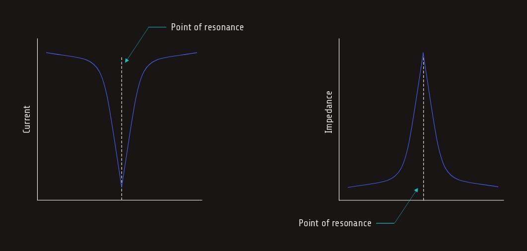
Graphs illustrating the decrease of current and increase of impedance in a parallel resonant circuit are shown in figures below.
 A parallel resonant circuit is applied in electronic systems where selecting, filtering, or rejecting specific alternating current (AC) frequencies is required: Radio Tuning - used in radio receivers and television tuners to select a specific frequency from ambient signals, Oscillator Circuits (Tank Circuits), RF Amplifier Loads, Frequency Filters ...
Bandwidth
The bandwidth for a parallel resonant circuit is determined in a manner similar to that used for a series resonant circuit. The bandwidth of a parallel circuit is determined by computing the frequency on either side of resonance at which the impedance is 0.707 of maximum.
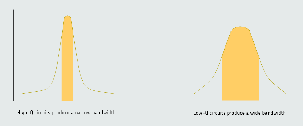
As in series resonant circuits, the Q of the parallel circuit determines the bandwidth.
Circuits that have a high Q will have a narrow bandwidth, and circuits with a low Q will have a wide bandwidth.