


Common industrial network protocol – PROFIBUS
PROFIBUS is an acronym for Process Fieldbus. It is a standard protocol that can be used to connect
sensors/transmitters, actuators, controllers, HMIs, VFDs, and more. The PROFIBUS protocol comes in two forms:
1. PROFIBUS DP (Decentralized Peripherals)
2. PROFIBUS PA (Process Automation)
PROFIBUS DP is among the most commonly
used network protocols in the industry. It is an industrial network protocol that reduces the
number of wires required to connect sensors and actuators by decentralizing the input and
output (I/O) modules. We can have up to 32 devices in the
PROFIBUS DP network per segment. The data transfer speed varies from 9.6 Mbps to 12 Mbps.
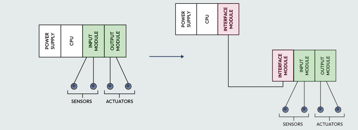
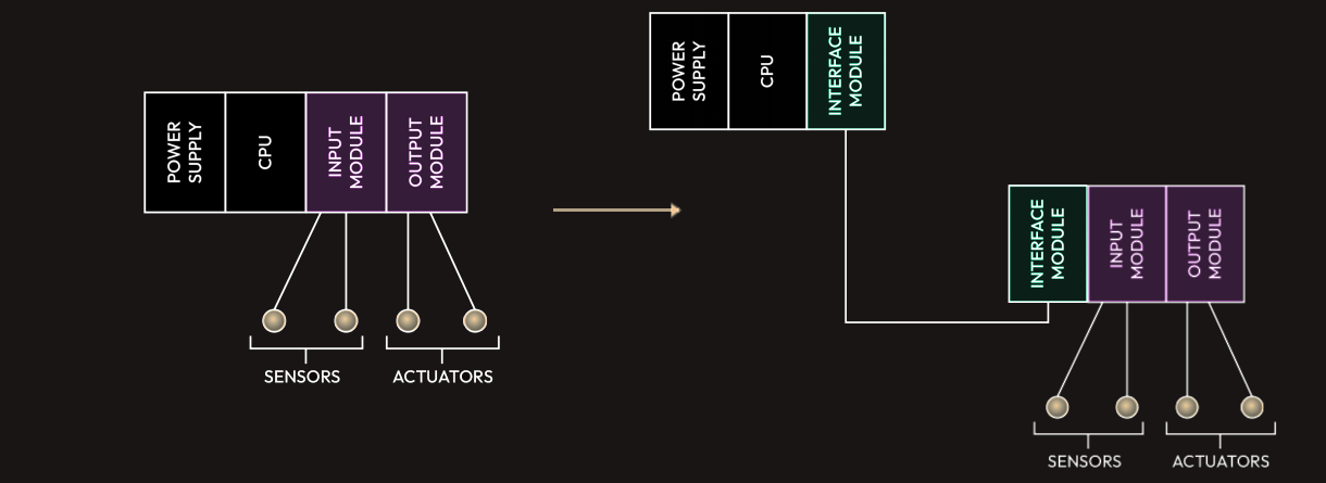 The diagram above on the right shows a decentralized control system in which a PROFIBUS cable
connects remote I/Os in the field to the PLC in the control room through an IM.
The diagram above on the right shows a decentralized control system in which a PROFIBUS cable
connects remote I/Os in the field to the PLC in the control room through an IM.
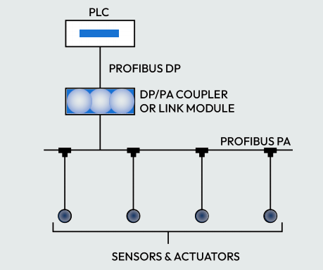
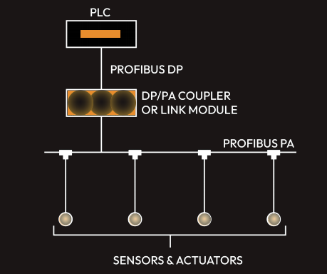
PROFIBUS PA is used to monitor process measuring devices
through a control system. Here, the I/O module that’s used in PROFIBUS DP is no longer
required, nor is any wiring between each sensor and I/O module. The sensors are connected
in a linear form to a single PROFIBUS PA bus. The network of sensors and actuators are then
connected to a PLC via a coupler and a single cable (PROFIBUS cable), as shown in the following
diagram. The segment coupler converts the PROFIBUS PA signals into a PROFIBUS DP signal.
The segment coupler is required because the PLC does not have a PROFIBUS PA port. It only
has a PROFIBUS DP port. PROFIBUS PA has a fixed data transfer speed of 32 Kbps.
Common industrial network protocol – Modbus
Modbus is an open protocol that can be used by any manufacturer or vendor without restriction. It
was originally designed in the mid-1970s by Modicon as a way to connect intelligent devices with
PLCs using a simple master/slave concept. Various vendors now manufacture their PLCs and other industrial devices to support the Modbus
protocol. Modbus can be referred to as the most commonly used industrial protocol.
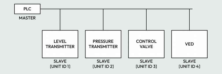
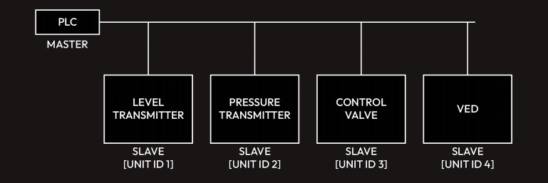
Modbus Remote Terminal Unit (RTU) is the most commonly used type of Modbus protocol. It uses binary coding and CRC error checking,
as well as a master and slave concept. A master device is a device that can request information from
the slave, while a slave is a device that provides information to the master. A slave will only transmit
information when it receives a command from the master to transmit. There can only be one master and
up to a maximum of 247 slaves, each of which has a unique address called a unit ID. The PLC is the master and will communicate with the field devices and VFD (slaves), each
of which has a unit ID. We can also have a SCADA/HMI as the master while the PLCs connected to
the SCADA/HMI are regarded as the slaves.
 The physical communication medium of Modbus RTU is RS232, RS422, and RS485.
RS232 is used for point-to-point topology. It allows communication between two devices (master and slave) at a distance of less than 15 m.
RS485 and RS422 are used to connect more than two devices on the same line at a distance greater
than 15 m, while RS485 is preferred for multiple devices connected over a long distance of about 1,200 m.
Modbus Transmission Control Protocol/Internet Protocol (TCP/IP) uses the server-client architecture.
We can have more than one device acting as the server and more than one device acting as the client, as shown in the following diagram.
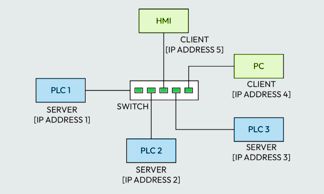
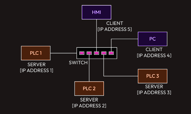 The clients and server are connected via a regular switch; the physical medium of communication is a regular Ethernet
cable. Each device in a Modbus TCP/IP network will have a unique IP address instead of a unit ID.
The clients and server are connected via a regular switch; the physical medium of communication is a regular Ethernet
cable. Each device in a Modbus TCP/IP network will have a unique IP address instead of a unit ID.
Common industrial network protocol – HART
The Highway Addressable Remote Transducer (HART) protocol is the world standard protocol and provides data exchange between smart/intelligent field devices and a controller (PLC, DCS, and so on) or handheld communicator. We can control and monitor HART-enabled field devices (sensors, transmitters, and actuators) with the HART protocol. In HART communication, a digital signal is superimposed on the traditional 4-20mA analog signal, allowing the 4-20mA analog signal to co-exist with the digital signal on the same two-wire loop without distortion. Hence, two signals are transmitted simultaneously – that is, the 4-20mA signal and the digital signal. The 4-20mA analog signal represents the measured variable regarding the temperature, pressure, level, or flow while the digital signals carry other device details, such as the device’s health, status, diagnostics alerts, and more.
Common industrial network protocol – PROFINET
PROFINET is an industrial Ethernet protocol designed to exchange data between devices and controllers
in industrial automation. It is the most well-adopted industrial Ethernet protocol. It can operate at a
higher speed than PROFIBUS because it is Ethernet-based. PROFINET is now becoming
a popular protocol that’s implemented in industries due to its high speed of operation (100 Mbps) and
flexibility. The PROFINET protocol can be implemented using the point-to-point, bus, or star topology.
Some of the differences between PROFINET and PROFIBUS are as follows:
• A PROFINET cable is a four-core cable, though a standard Ethernet cable can be used. A
PROFIBUS cable is usually purple and has two cores.
• PROFINET uses a standard RJ45 connector while PROFIBUS uses a PROFIBUS connector,
which looks like a standard DB-9 serial connector.
• PROFINET can have unlimited devices, while each device in a PROFIBUS network has a unique
address ranging from 1 to 127. Hence, 127 devices can be connected in a PROFIBUS network.
• The data transfer rate in PROFINET is 100 Mbps, while the maximum data transfer rate in
PROFIBUS is 12 Mbps.