


5. The address of an output (coil) can be used for input (NC or NO contact), which makes the input have the
same logic state (1 or 0) as the output; that is, if the output is ON (1), the input will be HIGH
(1), and if the output is OFF (0), the input will be LOW (0).
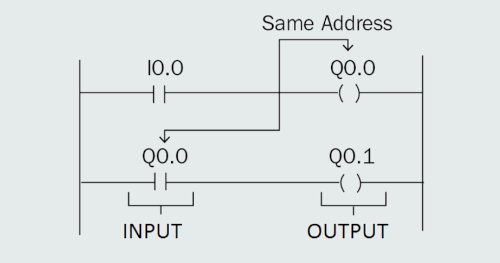
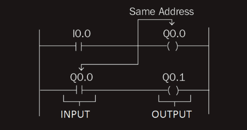 6. The address of an input cannot be used for output (coil).
Human Machine Interfaces (HMI)
A Human Machine Interface (HMI) is
usually integrated into a manufacturing line and other industrial processes to give users easy control
of the machines and to give them feedback on machine statuses. Integrating HMIs into such systems makes them more user-friendly. HMIs allow
us to start or stop the machine and even get feedback or status updates for the machine through
a graphical interface or touchscreen.
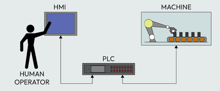
 HMIs allow humans to give commands to PLCs to control a process and also receive feedback from
PLCs about the process. With HMIs, the human operator can interact with, monitor, and control
machines via the PLC. The HMI is usually connected to the PLC via a communication cable, depending
on the protocol being used (Ethernet/IP, Profinet, Profibus, or Modbus). The PLC connects to the machine or sensors and actuators via cables, too.
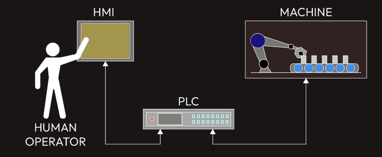
HMIs allow humans to give commands to PLCs to control a process and also receive feedback from
PLCs about the process. With HMIs, the human operator can interact with, monitor, and control
machines via the PLC. The HMI is usually connected to the PLC via a communication cable, depending
on the protocol being used (Ethernet/IP, Profinet, Profibus, or Modbus). The PLC connects to the machine or sensors and actuators via cables, too.
There are many HMIs
that we have and even use regularly without knowing them as HMIs. For instance, some cars have a
touchscreen interface through which the driver or passenger can control the air conditioning, heating,
sound, and other systems. These touchscreens are HMIs. The driver or passenger is able to interact with
the machine via the touchscreen-enabled interface. An HMI is simply an interface (usually graphical)
through which a human can control a machine.
HMI programming software is special software used for designing the graphical interface and writing
some code where necessary for the interaction between the user (human) and the machine. The
software is usually installed on the PC where programming will be done before it is downloaded to
the HMI panel via a communication cable, just as we do for PLCs. The IP address of the PLC must be different from that of the HMI, while the subnet mask must
be the same. There are different kinds of programming software for different brands of HMI panels.
Exploring SCADA
An HMI, as mentioned previously, is always close to the machine or Programmable Logic Controller (PLC)
– that is, an HMI is always local to the machine, and it is basically meant to control a single machine/PLC. SCADA also provides a means of monitoring and controlling along with other functionalities,
such as alarms, trending, and logging. However, the screen or PC for monitoring, controlling, or other
functionalities can be in a remote place – that is, far away from the machine – and we can have one
SCADA for more than one machine at different remote locations, unlike HMI.
SCADA is a system consisting of various hardware and software that work together to monitor and
control machines in an industrial process.
Supervisory control refers to a high level of overall control of several individual PLCs or multiple
control loops.
Data acquisition refers to the gathering of information and data from a process that is analyzed in
real time. Real-time data collection helps to reduce overhead costs, monitor an entire process, and
increase efficiency.
SCADA system helps to collect, analyze, and visualize data from equipment or a machine and also
provides a means of controlling the equipment or machine from a central location, which can be local
or remote.
 One production machine can be located in one geographical area (location A) while the other
machine can be in a different geographical area (location B). If a SCADA system is in place for the
two production machines, we can monitor the status of the two machines from a central location
and also control either of them.
One production machine can be located in one geographical area (location A) while the other
machine can be in a different geographical area (location B). If a SCADA system is in place for the
two production machines, we can monitor the status of the two machines from a central location
and also control either of them.
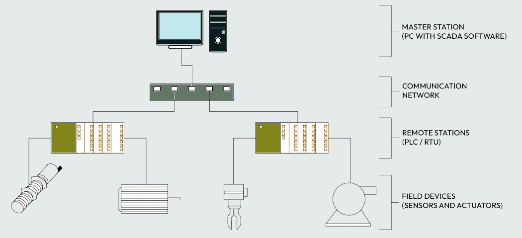
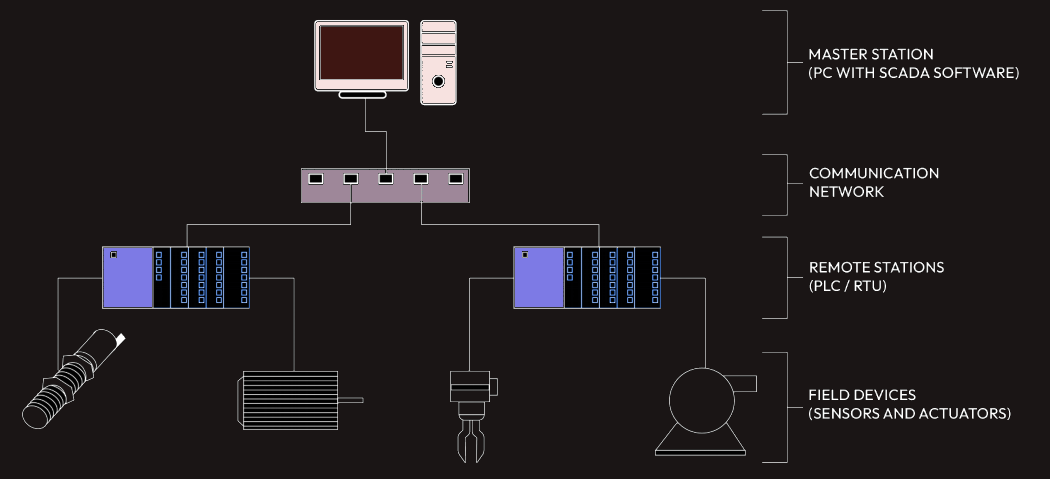
Overview of SCADA hardware
The hardware components of a SCADA system include the following:
1. Field devices: These are sensors, transmitters, and actuators that are directly connected to the
machine or plant and generate a digital or analog signal for monitoring. Sensors or transmitters
are for monitoring machine status or parameters, while actuators are for carrying out control
action on equipment or a machine.
2. Remote station: This can be a PLC or a Remote Terminal Unit (RTU). It is installed at a
remote site where the machine or equipment to be monitored or controlled is located. Field
devices (sensors, transmitters, and actuators) are connected to remote stations (a PLC or an
RTU) to allow monitoring and control from the host computer at a remote site via a network.
It gathers data through the sensors connected to it and transfers them to the host computer via
a network. It also transfers an electrical control signal from the host computer to the actuators
connected to it in order to perform the required control action.
3. Communication network: The main purpose of a communication network in SCADA is
to connect the remote stations (a PLC or an RTU) to the host computer (master station). It
allows the flow of information in a SCADA system. The communication medium for a SCADA
system can either be wired or wireless. A common wired medium is Ethernet. Various network
topologies (star, bus, ring, and so on) are available for use in a SCADA system, and various
network protocols (Profinet, Modbus, Profibus, and so on) are also available for use.
4. Master station: This can also be referred to as a supervisory station. It is the master computer
that runs SCADA software that provides the graphical presentation of the system. It runs the
HMI application that provides the graphical picture of the switches, sensors, transmitters,
pumps, and so on for monitoring and control purposes. Alarms can be set up to activate at
different predefined values. The entire control system at various plant sites can be monitored
and controlled through the GUI on the master station. A single computer can be configured
as a master station or networked to workstations or multiple servers. In a SCADA system that
uses multiple servers as a master station, one of the servers can be dedicated to an Alarm
Management System (AMS), and this can be referred to as an AMS console. An AMS console
consists of AMS software that provides an overview of alarms from various areas in the plant,
makes a quick response possible when there is an abnormal condition in the plant, and so on.
Basically, the master station collects information from the remote station (a PLC or an RTU),
represents them on a GUI for easy interpretation, generates an alarm, and also provides an
interface for various control actions that can be carried out at remote sites.
Common SCADA software includes the following:
• WinCC by Siemens
• FactoryTalk View by Rockwell Automation
• InTouch by Wonderware
• iFix by General Electric
• Citect SCADA by Schneider
• mySCADA