


Process control
In a very simple way, we can define process control as the technique of monitoring and adjusting a
process to yield the desired result.
In industry today, raw materials undergo a series of procedures (processes) before they become a
finished product. These processes need to be carefully monitored and adjusted to ensure quality products
are produced efficiently, economically, and safely. The monitoring of processes and the adjustments
necessary are usually automated using control systems.
Types of process control systems
Automatic process control can be categorized as one of the following:
- · Open-loop
- · Closed-loop (feedback)
- · Feedforward
- · Feedforward-feedback
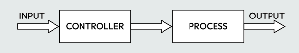
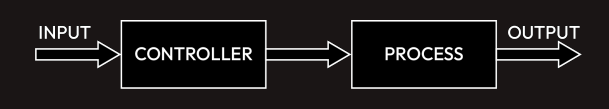
Open-loop control
In open-loop process control, the output does not change the control action. It has no sensor or
feedback system. An operation that depends on time is a typical example of an open loop; here, the output does not affect the control action. One example is a microwave oven heating food for a set time, regardless of temperature.
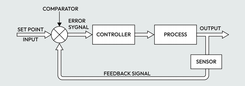
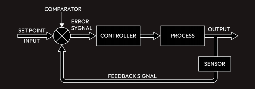
Closed-loop (feedback) control
In closed-loop process control, the output affects the control action. It has a sensor at its output that
is fed to its input as a feedback signal. The feedback signal is compared with a setpoint to generate
an error signal, which it uses to determine the required action necessary to drive the process to the
desired output or result.
 Feedback control is a common technology used in various industries. Feedback control is also common in our homes. Air conditioning is one common example. It has a
sensor that reads the temperature of the environment – this reading is fed to a controller that has a
setpoint and the setpoint is compared with the feedback signal to generate an error signal. The controller uses
the generated error signal to decide the control action needed to drive the compressor to ensure that
the desired temperature value is maintained. The sensor at its output enables it to determine whether
the desired temperature has been reached or not.
Feedback control is a common technology used in various industries. Feedback control is also common in our homes. Air conditioning is one common example. It has a
sensor that reads the temperature of the environment – this reading is fed to a controller that has a
setpoint and the setpoint is compared with the feedback signal to generate an error signal. The controller uses
the generated error signal to decide the control action needed to drive the compressor to ensure that
the desired temperature value is maintained. The sensor at its output enables it to determine whether
the desired temperature has been reached or not.
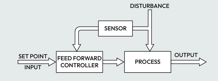
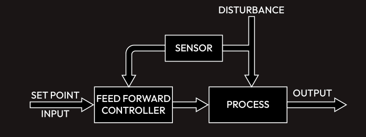
Feedforward control
This is a control system that foresees a disturbance and provides a control
action before the disruption affects the system. Feedforward control bases its control action on the state
of the load variable or input rather than the state of the output. It monitors
the load variable and takes any necessary action before the process variable (or output) deviates from
a setpoint.
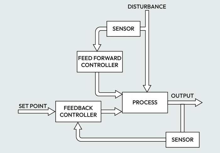
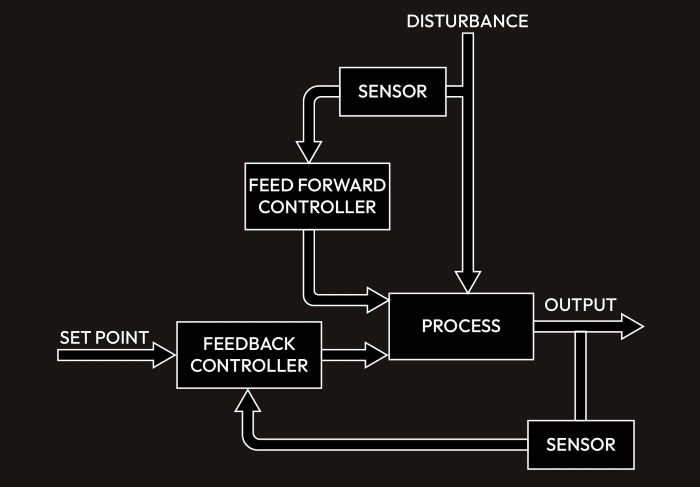
Feedforward-feedback control
Feedforward is not used by itself in industry – it is usually used with feedback control. The feedforward element
provides a quick response to any disruption while the feedback element provides the remainder of
the response by accurately acting on the error that eventually occurs. It utilizes both the feedforward
and feedback controller.
Process control terms
· Process: A process is any operation or event (or sequence of operations or events) that causes
a physical or chemical change to an input. Raw materials in industry undergo some kind of
series of operations, whether being heated, ground, or mixed, for example, before they resemble
a finished product.
· Sensors: A sensor is a device that senses or detects something – just as we have ears that hear,
eyes that see, a nose that smells, and a tongue that tastes. We have sensors that sense or detect
various physical properties such as temperature, pressure, level, or flow. Sensors basically
convert a physical property into an electrical quantity. Hence, the four common sensors used in process control are a temperature sensor, a pressure
sensor, a level sensor, and a flow sensor – some others include a pH sensor, speed sensor, or a
position sensor.
· Transmitters: A transmitter is a device that converts a signal produced by a sensor into a
standard signal (4 to 20 mA, 0 to 10 V, or 3 to 15 psi) that is applicable to process control.
The output signal from a sensor may be too small and need amplification or conditioning to
produce a standard signal. Hence, sensors are usually connected to a transmitter to produce a
standard signal output.
· Process variables or process values (PVs): This is the actual value or current value of the specific
quantity we are measuring. This can be temperature, pressure, level, flow, or another quantity.
· Setpoints: This can be referred to as the target value of the process variable. It is the value at
which we want the process variable to be maintained. For example, the target temperature of
a boiler can be referred to as the setpoint of the boiler.
· Errors: This is the difference between the process variable or measured value and the setpoint.
· Controllers: This is a device that provides the necessary control action to keep the process
variable at the setpoint. It acts on an error signal and provides the necessary control action
to the final control element to keep the error at zero so that the setpoint can be maintained.
· Control elements or final control elements: These are the devices that the controller operates
to keep the process variable at a setpoint. Examples include contactors, relays, solenoid valves,
pneumatic control valves, and variable frequency drives.
Unlike digital signals, which can only be in two states (0 or 1), analog signals have a continuous range
of values from the minimum to the maximum. They can present what’s between 0 (minimum, for
example, 0 V or 4 mA) and 1 (maximum, for example, 5 V, 10 V or 20 mA). When a voltage varies from
0 V to 10 V, or when a current varies from 4 mA to 20 mA, it is called an analog signal. Examples of
sensors and transmitters that produce an analog signal output are temperature transmitters, pressure
transmitters, and flow transmitters. Before a PLC can process analog values, it must be converted
into digital information first – this is done by the Analog-to-Digital Converter (ADC) in the analog
module of a PLC. One important feature of an analog module is its resolution in bits.
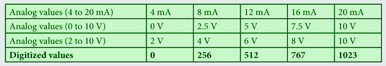
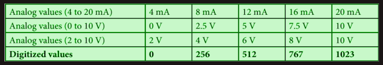 Basically, an 8-bit analog module will have 0 to 254 representing 4 mA to 20 mA or 0 V to 10 V
depending on whether the analog signal connected to it is a current or a voltage. A 10-bit analog
module will have 0 to 1023 representing 4 mA to 20 mA or 0 V to 10 V. A 12-bit analog module will
have 0 to 4095 representing 4 mA to 20 mA or 0 V to 10 V.
Basically, an 8-bit analog module will have 0 to 254 representing 4 mA to 20 mA or 0 V to 10 V
depending on whether the analog signal connected to it is a current or a voltage. A 10-bit analog
module will have 0 to 1023 representing 4 mA to 20 mA or 0 V to 10 V. A 12-bit analog module will
have 0 to 4095 representing 4 mA to 20 mA or 0 V to 10 V.