

Low-Pass and High-Pass Filters
Capacitors and inductors are components that impede a signal, the amount of which depends on the frequency of the signal. The capacitor delays voltage changes, and the inductor delays current changes. They are opposite in the way they react to the frequency of a signal. Capacitors block lower frequencies while letting higher ones through, whereas inductors pass lower frequencies while blocking higher ones. Let’s see what happens when we hook them up to a resistor.
Low-Pass Filters
Imagine first that we have two buzzers producing two different tones; one producing low-pitch sound and the other producing high-pitch sound, shown in figure below:
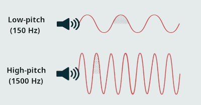
 Both buzzers can operate independently.
If we put a microphone nearby that picks up both sounds together as a single signal, we would have:

 So, using a filter we could separate low-pitch signal from high-pitch signal.


Let's apply an AC signal to the input of RC circuit shown in figure below.
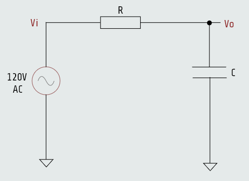
This circuit will allow low-frequencies to pass through, while reducing high-frequencies. It is called low-pass filter. The Input Voltage is applied across the entire series combination. The Output Voltage is taken specifically from across the Capacitor. This circuit is known as a low-pass filter, and all we really need to know to understand it is the voltage-divider rule and how a capacitor reacts to frequency.
The magic of the circuit lies in the Capacitive Reactance (Xc), Xc = 1/2πfC.
Voltage divider equation is: \(V_{out} = V_{in}\frac{R_2}{(R_1+R_2)}\), where R->\(R_1\) and C->\(R_2\) from the circuit on the left.
Here we have:
If R1↓ or R2↑ then Vout INCREASES.
If R1↑ or R2↓ then Vout DECREASES.
In this circuit, both resistance values stay constant at every frequency, there is no filtering, only amplitude of low-pitch and high-pitch signal changes. To build a real filter, we need R1 or R2 to change with frequency. This is where capacitors or inductors come into play; combining capacitor or inductor with resistor, we can build low-pass and high-pass filters.
At Low Frequencies: When f is small, Xc is very large (the capacitor acts like an open circuit). Because the capacitor has high resistance relative to the resistor, almost all of the input voltage drops across it. Thus, Vout ≈ Vin.
At High Frequencies: When f is large, Xc is very small (the capacitor acts like a short circuit). Because the capacitor has low resistance relative to the resistor, almost all of the input voltage drops across the resistor. Thus, Vout ≈ 0.
The capacitor acts like a short circuit to ground, essentially "draining" the signal away before it can reach the output.
This is known as a low-pass filter because it passes low frequencies while reducing or attenuating high frequencies.
Vout = (Xc/|Z|) Vin
Xc = 1/(2πfC)
|Z| = √(R2 + Xc2)
...
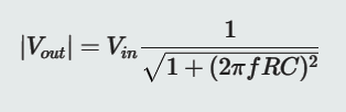
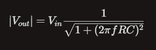 From this equation we see that high frequencies are weakened (Vout ↓) while low frequencies pass more easily (Vout ↑).
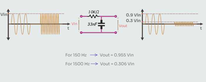
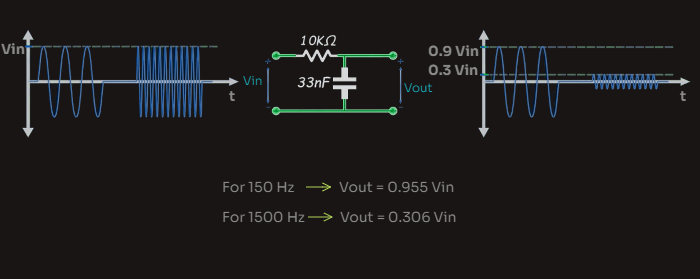
We can make a low-pass filter with an inductor and resistor, too. Given that the inductor behaves in a way that is opposite of a capacitor, we will swap the position of the components. That’s because the inductor (being the opposite of a capacitor) passes the lower frequencies and blocks the higher frequencies. It performs the same function as the low-pass RC circuit but in a slightly different manner.
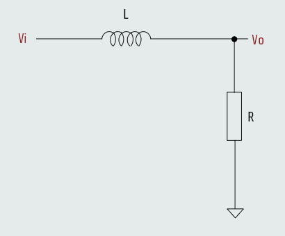
Vout = (R/|Z|) Vin
XL = 2πfL
|Z| = √(R2 + XL2)
...
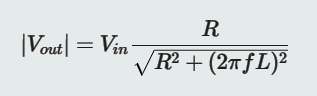
 We still have a voltage-divider circuit. At low frequencies the inductor offers very little opposition (low inductive reactance), allowing the signal to pass easily through to the resistor output. At high frequencies the inductor's opposition increases significantly, blocking the high-frequency signals and dropping most of the voltage across itself, which reduces the output at the resistor. High frequencies are weakened (Vout ↓) while low frequencies pass more easily (Vout ↑).
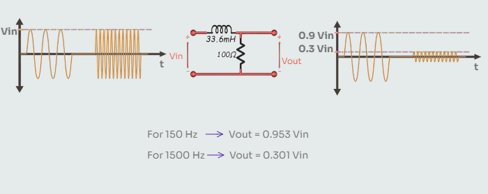
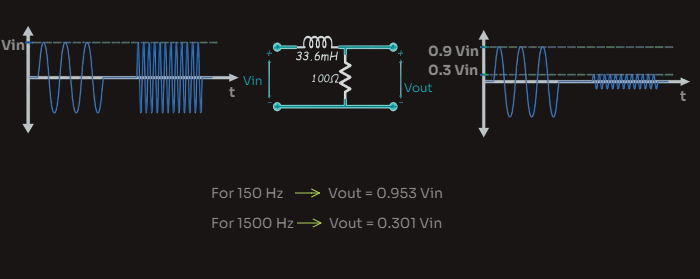
In the low-pass filter circuits, as the frequencies sweep from low to high, the capacitor starts out as an open and moves to a short while the inductor starts out as a short and becomes an open. By positioning these components in opposite locations in the voltage-divider circuit, we create the same filtering effect. The ratio of the voltage divider in both types of filters decreases the output voltage as frequencies increase, which lets the low frequencies pass and blocks the high frequencies.
A first-order RC low-pass filter reduces high frequencies gradually, so some high-frequency signal still remains. If we want much stronger filtering, we need higher-order filters, such as second-order or third-order filters.
Let's see now what might happen if we swap the position of the components in these circuits.
High-Pass Filters
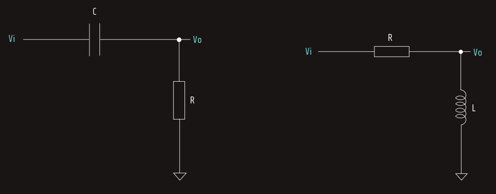
Swapping the capacitor and the resistor in the low-pass circuit creates another type of circuit called a high-pass filter.
This actually means the circuit passes high frequencies while blocking low ones.
The magic of the circuit also lies in the Capacitive Reactance (Xc), Xc = 1/2πfC.
At low frequencies, Xc becomes very large. The capacitor acts like an open circuit (a broken wire), blocking the signal from reaching the resistor and the output, Vout ≈ 0.
At high frequencies, Xc becomes very small. The capacitor acts like a short circuit (a plain wire), allowing the signal to pass straight through to the output resistor, Vout ≈ Vin.
The capacitor acts like a larger resistor at low frequencies, making the voltage divider knock down the output. At higher frequencies the capacitor passes more current as it becomes a short, causing a higher voltage at the output. 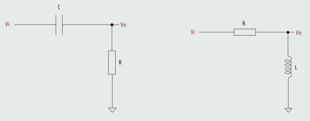
 Vout = (R/|Z|) Vin
Xc = 1/(2πfC)
|Z| = √(R2 + Xc2)
...
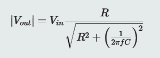
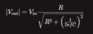
The inductor version is the inverse, circuit-wise, of the RC high-pass filter.
Vout = (XL/|Z|) Vin
XL = 2πfL
|Z| = √(R2 + XL2)
...
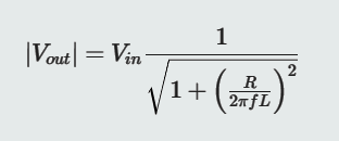
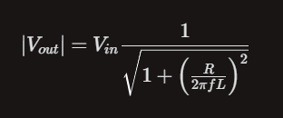 The high-pass and low-pass filters take advantage of the frequency response of either a capacitor or an inductor. This is done by combining them with a resistor to create a voltage divider that attenuates the unwanted frequencies while allowing the desired ones to pass.
- · In an RC low pass, the capacitor is in parallel with the output. At high frequencies, Xc is low, so it shorts the signal to ground.
- · In an RL low pass, the inductor is in series with the input. At high frequencies, XL is high, so it "blocks" the signal from ever reaching the output.
High Pass:
- · In an RC high pass, the capacitor is in series with the input. At low frequencies, Xc is high, so it "blocks" low frequencies and passes high frequencies.
- · In an RL high pass, the inductor is in parallel with the output. At low frequencies, XL is low, so it shorts low frequencies to ground, while staying "open" for high frequencies.
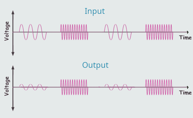
A first-order RC high-pass filter reduces low frequencies gradually, so some low-frequency signal still remains. If we want much stronger filtering, we need higher-order filters, such as second-order or third-order filters.
Some cool things happen when we put the two reactive elements together. We can create notch- and band-pass filters where a specific band of frequencies is knocked out, or a specific band is passed while all others are blocked, and the phenomenon of resonance also occurs in what is called a tank circuit, where there is a capacitor combined with an inductor.
The Magnetic Field
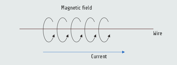
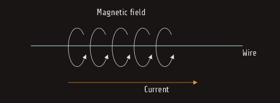
Back in the 1820s, a man by the name of Hans Oersted noticed his compass read strangely every time he switched on a current in a wire. Eventually it was discovered that a moving electron (such as the current in a wire) creates a magnetic field perpendicular to the direction of electron movement.