


Delta Star and Star Delta Transformation
Standard 3-phase circuits or networks take on two major forms with names that represent the way in which the resistances are connected; a Star connected network which has the symbol of the letter, Υ (wye) and a Delta connected network which has the symbol of a triangle, Δ (delta).
If a 3-phase, 3-wire supply or even a 3-phase load is connected in one type of configuration, it can be easily transformed or changed it into an equivalent configuration of the other type by using either the Star Delta Transformation or Delta Star Transformation process.
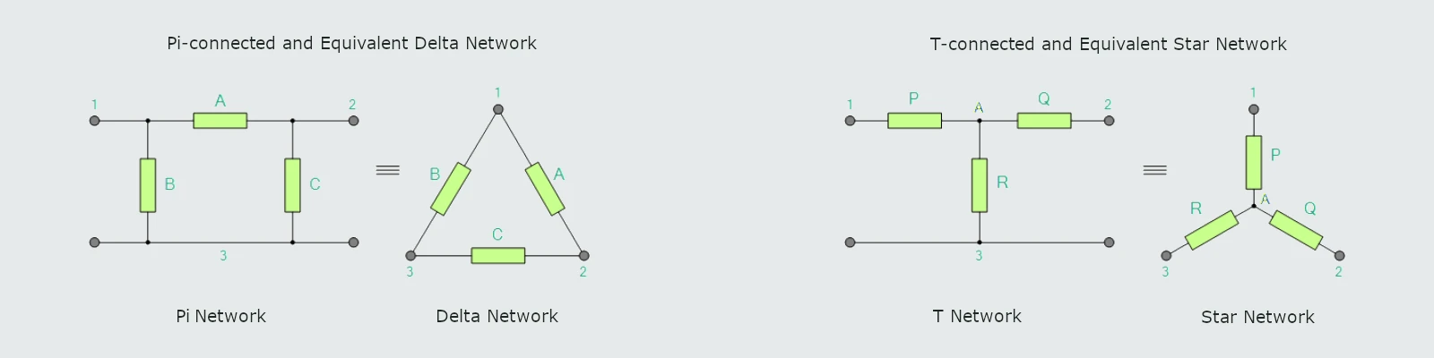
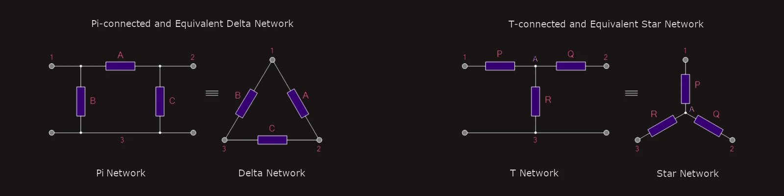 Having now defined what is a Star and Delta connected network, it is possible to transform the Υ into an equivalent Δ circuit and also to convert a Δ into an equivalent Υ circuit using the transformation process.
This process allows us to produce a mathematical relationship between the various resistors giving us a Star Delta Transformation as well as a Delta Star Transformation.
Having now defined what is a Star and Delta connected network, it is possible to transform the Υ into an equivalent Δ circuit and also to convert a Δ into an equivalent Υ circuit using the transformation process.
This process allows us to produce a mathematical relationship between the various resistors giving us a Star Delta Transformation as well as a Delta Star Transformation.
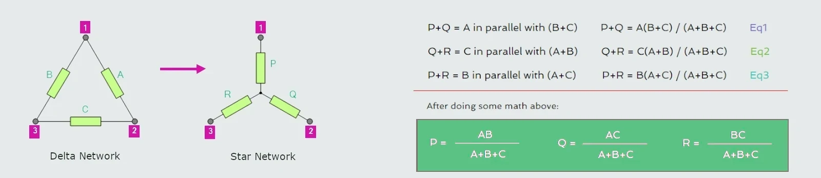
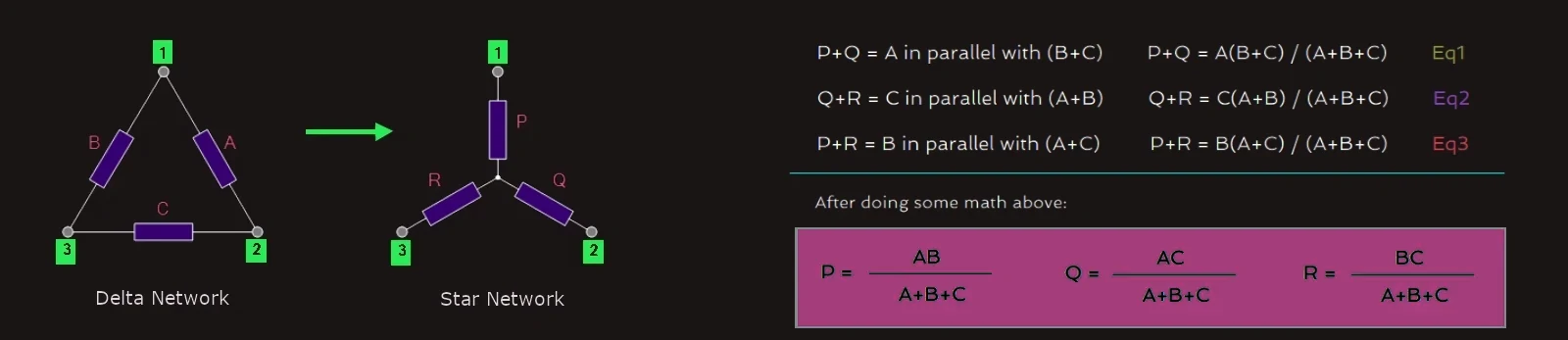
Delta Star Transformation
To convert a delta network to an equivalent star network we need to derive a transformation formula for equating the various resistors to each other between the various terminals.
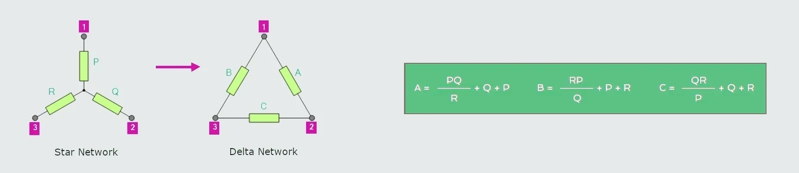
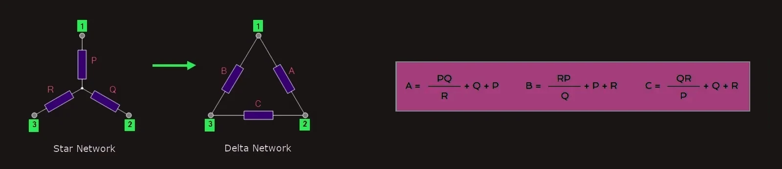
Star Delta Transformation
The transformation from a Star network to a Delta network is simply the reverse of above.
By rewriting the previous formulas a little we can also find the transformation formulas for converting a resistive star connected network to an equivalent delta network giving us a way of producing the required transformation.
Both Star Delta Transformation and Delta Star Transformation allows us to convert one type of circuit connection into another type in order for us to easily analyze the circuit. These transformation techniques can be used to good effect for either star or delta circuits containing resistances or impedances.
Nodes, Branches and Loops
Nodes, branches and loops are the three fundamental elements that make up an electric circuit allowing us to apply circuit solving techniques to simplify complex networks.
· Node – a node is a junction, connection or terminal within a circuit where two or more circuit elements meet.
· Branch – a branch is a single or group of components such as resistors or sources which are connected together between a pair of nodes.
· Loop – a loop is a simple closed path in a circuit in which no circuit element or node is encountered more than once.
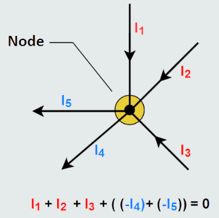
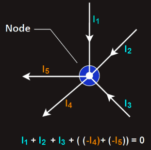
A Node, or nodal point, in an electrical circuit is a point where two or more circuit elements are connected together. Nodes in a circuit represent a junction where current can split or combine.
The currents flowing into and out of a nodal point are called branch currents, since a branch is a single path in a network with a node at each end. Thus the branch currents flow between a pair of nodes.
 We can assume all points within a node are at the same voltage potential for all components connected directly to that node. That is, every connection of every component that is physically connected to the same node is at exactly that same voltage value. There’s no potential difference across that single node even when separated into many junctions.
Nodes in a circuit tell us where components connect and how current can split.
We can assume all points within a node are at the same voltage potential for all components connected directly to that node. That is, every connection of every component that is physically connected to the same node is at exactly that same voltage value. There’s no potential difference across that single node even when separated into many junctions.
Nodes in a circuit tell us where components connect and how current can split.
A Branch is any single path in a circuit that contains just one circuit element, or several elements which are joined together between two nodes (junctions). Thus branches of a circuit can result with two or more components in series. Then essentially, a branch is the part of the circuit where current has only one path to follow between the two two nodes (or junctions).
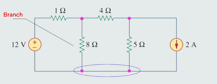
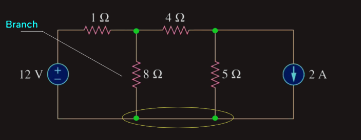 A branch represents any single two-terminal element such as a voltage source or a resistor with a node at each end of that element. Branches of a circuit give us the segments along which current flows and the voltage drops between those connections.
A Loop is any simple closed path within a circuit that starts and ends at the same node. In other words, a loop forms a complete closed circuit which passes through any node only once, starting and ending at the same point.
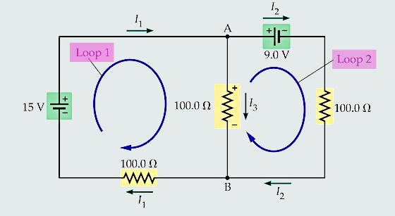
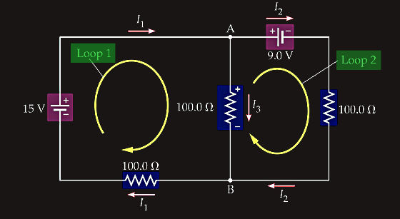 Also, a loop does not have to include any component, it just has to be a closed path. Loops and meshes (a loop in a circuit that does not contain or enclose any other loops within it) let us trace paths through the circuit to understand how voltages add up or cancel out.
The concept and idea behind nodes, loops and branches are fundamental in helping us understand how electricity flows around a network so that we can apply Kirchhoff’s Voltage Law, (KVL) and Current Law, (KCL) for both analysing and solving complex circuits.